Continue to Site

Welcome to EDAboard.com

Welcome to our site! EDAboard.com is an international Electronics Discussion Forum focused on EDA software, circuits, schematics, books, theory, papers, asic, pld, 8051, DSP, Network, RF, Analog Design, PCB, Service Manuals... and a whole lot more! To participate you need to register. Registration is free. Click here to register now.

adjustable delay unit (555 timer)

Status
Not open for further replies.

Swagger_Dancer

Newbie level 3
Joined
Apr 19, 2020
Messages
4
Helped
0
Reputation
0
Reaction score
0
Trophy points
1
Activity points
42
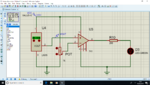
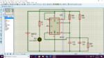
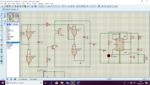
I am using proteus isis to build my adjustable delay unit with a 555 timer connected to it. The resisters and capacitors have values when changed will delay the current to make it turn off after so long. No matter how many values I changed it will not turn off and continues to light the LED. I don't know if I have wired it wrong either. It also needs to attach to my audio generator to turn off the alarm, when connected to that the alarm stays sounded
 

Attachments

  • 2020-04-15 (2).png
    2020-04-15 (2).png
    133.4 KB · Views: 174
  • 2020-04-19 (3).png
    2020-04-19 (3).png
    160 KB · Views: 163

Hi,

100nF to ground missing on control pin...

I'm uncertain of your 555 circuit objective, and question. Does the 555 trigger at power on and then turn off when timed out?

Monostable is set for 11 seconds? You have pin 2 trigger tied to a fixed voltage once the capacitor is charged up. Measure the voltage at trigger pin and see if it is below 1/3rd supply voltage. For a POR one-shot, try a 10k resistor from V+ into a 100pF capacitor, the other end of the capacitor goes into a junction of pin 2 and a 100k resistor to V+.

Can you describe what the 555 does to the alarm with different words, please, and explain what the alarm circuit logic does?

- - - Updated - - -

If the alarm NOR gate + BJT circuit is an oscillator to drive the buzzer/speaker, you could swap it for a 555 astable circuit whose reset pin is controlled by your 555 11-second monostable circuit. Depending on when the alarm needs to be on or off, an NPN BJT common collector (inverter) or logic gate NOT, or one NOR with the inputs tied together might need to be put between 555 monostable output and astable reset pin.
 

Hi,

Basically, this 555 timer should be connected to the audio generator so when it is activated, it will turn the alarm off after 1-2 minutes. I didn't mention about the trigger circuit. I have built a trigger circuit also that will activate when it hits 30 degrees (0.3V), do I need to connect the trigger circuit to the 555 timer so it has a voltage to turn on?
 

Hi,

In principle, yes. The input signal to trigger needs to be lower than 1/3rd V+ for less time than the 555 output signal. The 10k-100pF-100k makes a short low pulse when triggered by a long signal. T 555 output high = 1.1 * R * C. A 1 or 2 minute output pulse duration is 1.1 * 100uF * 550kiloOhms or 1.1MegaOhms.
 

Ah, yes so after I connect my trigger circuit to my adjustable delay circuit, will I just need to chance the values of the resisters or have to re-wire to make it turn off after 1 minute?
 

Hi,

Please clarify a doubt I have about your wording: Why do you call it an "adjustable delay circuit"?

The 555 circuit will be a fixed ~60 seconds with 100uF and 550k or ~120 seconds with 100uF and 1.1M.

In principle, you will probably need to wire it as described:

V+_________V+
10k-100pF-100k-pin 2.

Please show the trigger circuit you will use into the 555 trigger pin 2.
 

Hi,

As I'm unsure of what you want, and a picture says more than words, here are two schematics with explanations for you to say which is the circuit you are making.

I use the TLC555 as it works well in simulations and when converted to a real circuit with the SE/SA/LMC 555 it works as simulated. The first transient results were done with a 1uF timing capacitor and 550k to show trigger pin function. I hope the explanations are helpful and not unnecessary and therefore patronizing - I do not know your level of experience. Quirk of simulator is it represents timer RC as less than R x C but 555 is 1.1 x R x C :), maybe the capacitor charging speed-up section affects the timing a little but it shouldn't. Anyway, that's the fun of the 555 - timing is not precise.

Hope they are useful and clear to understand.

**broken link removed**
 

d123, your attachment does not work. Every attachment with an attachment number like your, does not work. Attachments work fine when they are attached as a thumbnail.
 

Attachments

  • thumbnail.png
    thumbnail.png
    2.6 KB · Views: 136
  • Like
Reactions: d123

    d123

    Points: 2
    Helpful Answer Positive Rating
Hi,

This is my trigger circuit that turns on when it hits 30 degrees, I haven't put all three circuit together yet to make a whole circuit, I would imagine I would need to connect it with the 555 timer to make it switch off after 120 seconds

I said about the re-wiring because I can change the values of the resistors and capacitors but it never turns off after so many seconds or minutes
 

Attachments

  • Screenshot (2).png
    Screenshot (2).png
    118.7 KB · Views: 165

Thanks for letting me know. I think it's because I got logged out writing the reply. No, apparently there's a problem with my awful phone netwotk provider's weak signal or 417kb is too big for forum, yet 800kb pdfs aren't. Nice waste of my time and limited phone battery after an awful day of walking 16km in the rain for a little food shopping and dedicating two hours of my time to this thread. Super, just super...

- - - Updated - - -

How drole, six attempts later, the jpg appears....
 

Attachments

  • 555 1 OR 2 MINUTES EDABOARD.JPG
    555 1 OR 2 MINUTES EDABOARD.JPG
    415.7 KB · Views: 138

A lousy old 741 opamp is 52 years old and will not do anything with your power supply voltage that is only 5V. The datasheet for all circuits on the datasheet of a 741 opamp shows a +/-15V (30V total) supply.
The 741 opamp also will do nothing since the input voltages are much too close to its negative supply voltage, it usually has an additional negative supply voltage feeding pin 4, then its input voltages will be far from either supply voltage.

What is the "Vout" from the LM35 also going to feed?
 

Hi,

You probably need to rethink that trigger circuit... I think you need to contemplate supply voltages, how battery voltage drops with use, and how inputs work and their voltage level requirements (datasheets are your friend).

Suggestions:
Put a voltage divider on the 9V supply to get the 5V needed for the LM35. Place a 1uF and a 100nF capacitor from V+ (9V) to ground around the voltage divider for a stable supply voltage. If the 9V is a battery that will quickly fall to 7V use an LDO or a TL431 to generate the LM35's 5V supply.

You need a comparator, not an op amp, for the trigger circuit... Anyway, if you have a 741, perhaps you have an LM324 - much nicer to use: +2V to +30V supply and input includes ground. LM35 at 30C is 0.3V - 741 inputs are minimum requirement of 1.5V above lowest supply voltage, the 741 won't 'see' the LM35 input of 0.3V...

You could be 'clever' and use an LM324 with a gain of ~4 and feed that into the 555 reset pin then the alarm is only on over 30C but that would be fussy for you to get right, I think, looking at your circuits.

Other option, easier: get a comparator, or use an op amp whose inputs include ground as a comparator, make the 0.3V reference with another voltage divider and have the comparator set up to go low at >0.3V. Use the comparator output to trigger the 555 with circuit A or circuit BI showed you in a previous post.

If I think of anything better, I will come back.
 

Hi,

Don't know if these help at all. Used LM324 as no point wasting time with Lm/UA741 unless you use a dual supply, e.g. two batteries in series to get +9V and - 9V so it can sense 0V to 1V of LM35.

Notice nasty spike of 555 trigger pin when pulls high again, I couldn't get rid of it...

Advise against using a battery to generate a voltage reference as already stated - it will change as the battery drains.

LM324 reference and hysteresis can be played with to perfect when it triggers. I chose 270mV as simulation showed best response time for 30C (0.3V).

555 1 OR 2 MINUTES EDABOARD LM324.JPG

555 1 OR 2 MINUTES EDABOARD 555 PLUS 324.JPG
 

Status
Not open for further replies.

Part and Inventory Search

Welcome to EDABoard.com

Sponsor

Back
Top