nikosnte
Junior Member level 3
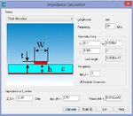
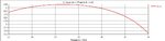
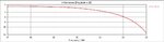
Hello everyone, recently i simulated a microstrip line in CST Microwave Studio with width 1.53564[mm] and the characteristic impedance value of this line with a substrate with epsr=3 at 30[GHz] is 12.2 ohms as it can be seen in the correspoding picture attached. Because i wanted to test the S11 behavior when the line is terminated in a load with the same impedance and when it's not, first i placed a load wich i selected a lumped element(first i picked the two necessary edge centers) RLC serial with R=12.2 ohms(C=0 & L=0) and later on, i placed the same load but with R=50 ohms and ran the simulation for both loads. As for the source, i placed edge discrete port at both simulations with reference impedance 12.2 ohms. The S11 parameter at the second simulation appears to have smallest S11 than the first simulation at many frequencies with a much bigger drop although the line is supposed to be mismatched because of the difference of port-load impedance. Why is this happening?
PS: the first S11 pic corresponds to the 12.2 ohms load and the second to the 50 ohms load and there are pics of the mlines too.
PS: the first S11 pic corresponds to the 12.2 ohms load and the second to the 50 ohms load and there are pics of the mlines too.
Attachments
-
 Screenshot_5.jpg55.5 KB · Views: 224
 -
 load12.2 (3).jpg60.6 KB · Views: 223
 -
 load12.2 (2).jpg62.8 KB · Views: 239
 -
 load12.2.jpg51.8 KB · Views: 182
 -
 load12.2 (4).jpg78.7 KB · Views: 252
 -
 load50 (4).jpg68.6 KB · Views: 193
 -
 load50 (3).jpg68.1 KB · Views: 204
 -
 load50.jpg57.9 KB · Views: 196
 -
 load50 (2).jpg64.1 KB · Views: 260


