Continue to Site

Welcome to EDAboard.com

Welcome to our site! EDAboard.com is an international Electronics Discussion Forum focused on EDA software, circuits, schematics, books, theory, papers, asic, pld, 8051, DSP, Network, RF, Analog Design, PCB, Service Manuals... and a whole lot more! To participate you need to register. Registration is free. Click here to register now.

Simple a.m modulator output not what I expect?

Status
Not open for further replies.

voxmagna

Newbie level 5
Joined
Apr 19, 2020
Messages
9
Helped
0
Reputation
0
Reaction score
0
Trophy points
1
Activity points
89
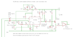
Hi, I'm very rusty building from schematics. I want an a.m modulator for a 40kHz carrier with a modulating frequency of 1kHz. I've tried 3 or 4 different schematics and all give an output I didn't expect. I expect positive peaks of the envelope to correspond with positive going peaks on the negative half of the envelope with both troughs approaching zero for 100% mod. depth.

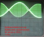
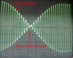
I built the simplest single transistor schematic - 40kHz sine carrier feeds the base and a 600 ohm line transformer in the emitter is fed with 1kHz. What I see at the collector on the 'scope is positive going peaks aligning with negative troughs. I've attached a screenshot with the 1kHz modulation superimposed for clarity. I must be a dumbo not understaning what's going on, because I see the same thing with a 2 transistor totem pole, 3 transistor long tailed pair or op-amp designs.

Can somebody explain what I'm missing?
 

Attachments

  • IMG_2059-small.jpg
    IMG_2059-small.jpg
    80.4 KB · Views: 117

We need to see a schematic to be sure but from what you describe you are attempting to add the transformer output to the overall supply of the modulator stage. Whether the transformer output adds or subtracts from the carrier depends on the phase of the secondary winding. It may be that an increase in your modulating waveform voltage is subtracting from the signal instead of adding. There is also some visible additional phase shift but that could be down to the transofrmer or even the way you have the scope triggered.

Brian.
 

You do not realize a Modulator, instead it looks like a Mixer Output.It will more and less will act as modulator but it is not a real modulator..
You sum up 2 carriers at emitter junction and this superposed carriers simultaneously control the collector current by surely some nonlinearities.
 
Thanks for quick replies.

I agree it looks like a mixed output. I used a transformer in the emitter of the BF194 as a last resort because i've tried similar schematics using a J-FET or transistor and all behave the same. As I understand it I should be controlling the transistor gain to get true a..m. Here's a link to the schematic. It makes no difference if I remove the transformer from the emitter leg and connect the AF source to my 50 ohm 1kHz sig. gen. This single transistor design is very simple & I don't expect to get 100% mod. depth. Also the bias resistors and carrier drive level needs tinkering with, but the waveform out still stays the same.

http://www.ktulabs.com/2018/01/amplitude-modulation.html

am1.jpg

This is so stupid I wondered at first if it was my 'scope triggering, but the output is real.

Thanks
 

If you insert the Audio Signal ( Lower Frequency) as parallel, you obtain a Mixer.If you insert the Audio Signal in series, the circuit will work as Modulator.
These are not same..There will be a RF Current ( Higher Frequency) then this current will be controlled by Modulating signal.
 
There's probably a small modulator effect (AF*RF output term), but it's hidden under the max larger linear AF and RF terms. That's the typical behaviour of a single transistor mixer. The AF term can be simply removed by a high pass filter. But the achieved modulation index is very small, not more than a few percent.
 
Thanks. I've looked at several 'simple' a.m modulators now and they all post the classic waveshape and not what I get when I try their schematics. I'm getting the impression many posted schematics haven't been built. I might experiment with the MC1496 but was hoping to avoid negative supply rails for what I thought would be simple project.

I did calculate the HP filter for 40kHz and yes you are correct, the mod. depth wasn't near the 80-90% I was looking for. For my relatively low carrier frequency I expected an audio op amp with a j-fet input controlled attenuator to work. But as soon as you add some gain, even 40kHz struggles to get through without distortion due to the limited slew rate.
 

you are measuring the AF signal PLUS the RF o/p, try measuring just the RF ... ....!
 
Duh... I'll try adding a 40kHz filter to the output. Thanks
 

hoping to avoid negative supply rails

Assuming your waveforms are in the positive region...
Consider modulation by attenuation of the carrier. It works differently from altering gain.

AM modulation by attenuation (PNP diverts signal).png

Percentage of modulation can be as much as 100%. Simply change bias voltage at the PNP transistor.

This illustrates the concept. It's not perfect. The sine shape is misshapen at middle amplitudes. More effort is needed to operate the transistor in a smoother manner.
 

More effort is needed to operate the transistor in a smoother manner.
Thanks, I'm working on that.
 

I've been quiet but working hard on this! There are so many schematics on the web that either mislead or just don't work when you breadboard them. The outline to my project is a.m modulating a 40kHz carrier with 625Hz (or 1kHz) to use as a driver signal in an H bridgeamplifier to drive high level signals into an ultrasonic emitter. This will be running in a sealed enclosurs with an external a.m detector to detect air leaks. I'm using a.m so I can vary the mod. amplitude and RX sensitivity to detect tone (air leaks) with headphones in addition to using a moving coil meter.
 

Attachments

  • MC1496 single rail a.m modulator2.png
    MC1496 single rail a.m modulator2.png
    90.4 KB · Views: 124
  • Mod-output-small.jpg
    Mod-output-small.jpg
    158.6 KB · Views: 126
  • No-phase-reversal-small.jpg
    No-phase-reversal-small.jpg
    138.8 KB · Views: 82

Status
Not open for further replies.

Part and Inventory Search

Welcome to EDABoard.com

Sponsor

Back
Top