Continue to Site

Welcome to EDAboard.com

Welcome to our site! EDAboard.com is an international Electronics Discussion Forum focused on EDA software, circuits, schematics, books, theory, papers, asic, pld, 8051, DSP, Network, RF, Analog Design, PCB, Service Manuals... and a whole lot more! To participate you need to register. Registration is free. Click here to register now.

Replacing relay to trigger a device input

Status
Not open for further replies.

seyyah

Advanced Member level 2
Joined
Oct 7, 2001
Messages
646
Helped
8
Reputation
16
Reaction score
8
Trophy points
1,298
Activity points
6,233
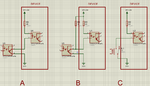
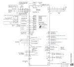
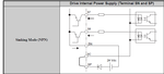
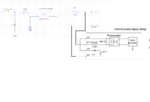
I have a device to control shown in the attachment. I need to send commands to the inputs of the device. Inputs of the device are shown in the attachment. They are triggered by applying gnd to the inputs of the device. I have access only to the 2 terminals of the input; command and gnd(common). Normally I do it by using relay. But I want to replace it with a semiconductor device. As shown in figure; scenario A is not working but B is working. In order to apply scenario B I need 3rd terminal of the device: VDD. And that is not an option. What can I do? Thanks.
 

Attachments

  • circuit.png
    circuit.png
    112.4 KB · Views: 141

Why doesn’t A work? Are you driving the external optocoupler hard enough? Does the optocoupler sink enough current to turn on the internal led? you don’t provide any part numbers or specs...

Further, there is no reason B should work, but A doesn’t. Have you drawn this correctly?
 

Hi,

I fully agree with Barry.

But my main question is:
Why two optocouplers in series at all?
I see neither the need nor a benefit. One isolation should be sufficient.

--> thus I'd just use a bjt. Or open collector drivers like ULNxxxx
I'd avoid a relay ... it just causes trouble.

Klaus
 

I don't have access to the external device. I derived the device inner circuit from its manual. So I don't know what's exactly in it but it's an optocoupler circuit. My circuit on the other hand has PC817 as a optocoupler. I drived it directly from microcontroller (3V3) with a series resistor of 220 ohms (I could not go further due to limitations). In A, when I drive the output, pin 5 of the optocoupler shows a ~9V like it did not fully turned on and when I cut off the output I measure ~12V at the same point. On the other hand, in B situation, I measure below 1V at turn on and 24V at turn off at pin 5 which is OK. I thought exactly like you at the beginning but my experiments gave me this result.

- - - Updated - - -

I did not want to connect both gnds since I don't know exactly how the external device uses it.

- - - Updated - - -

PC817 C version
 
Last edited:

Hi,

external <--> internal:

There is this "magic" device.
It has some circuit inside. This is called "internal"
All the other circuitry connected by you is called "external"

Usually every "device" comes with a datasheet. It tells you about voltages, currents and all the wiring informations.

If this "device" is some high quality industrial device, then the internal optocoupler is for galvanic isolation and you may rely on it.

********

I´m not the friend of solving useless riddes. You say there is a manual, so it should be no problem for you to say what this "device" is. Brand name and exact type. A link to the manual could be useful, too.

Klaus
 

I don't have access to the external device. I derived the device inner circuit from its manual. So I don't know what's exactly in it but it's an optocoupler circuit. My circuit on the other hand has PC817 as a optocoupler. I drived it directly from microcontroller (3V3) with a series resistor of 220 ohms (I could not go further due to limitations). In A, when I drive the output, pin 5 of the optocoupler shows a ~9V like it did not fully turned on and when I cut off the output I measure ~12V at the same point. On the other hand, in B situation, I measure below 1V at turn on and 24V at turn off at pin 5 which is OK. I thought exactly like you at the beginning but my experiments gave me this result.

- - - Updated - - -

I did not want to connect both gnds since I don't know exactly how the external device uses it.

- - - Updated - - -

PC817 C version

This still makes no sense. Think about it. Your external transistor can’t drive low with a small load, but if you increase the load (external resistor) then it can. Transistors just don’t work that way.

I still question your design. The PC817 has minimum current transfer ratio of 50%, which means with a 5ma input, the output could be 2.5 mA, maybe not enough to turn your internal opto on. The external LED has about a 1.5 V drop, which means at most you’ll be driving (3.3-1.5)/220=8mA; it’s probably less since you’re not going to get 3.3 V from your uC.

It’s also suspicious that when your device is “off” you see 12V at the collector. That most certainly is not “off”.

As Klaus suggests, just use a BJT, the optocoupler is redundant.
 

Hi Klaus however you want to name it, it is OK. There is not a single brand device. I'll use it with ac drives of multiple brands. These are for refence speed digital inputs of the ac drive. My experiment was on an iastar as320 brand drive of china which I could not find an english manual just now. But I'll use from yaskawa, meiden, fuji to local brands. And yaskawa manual verifies you (also my first assumption). So what is the problem here? Say I use optcoupler (because my current prototype has optocoupler installed, I may revise it in the next edition), what may be the solution here? Driving the optocoupler with a larger current? Or is there a problem with the inverter itself?

**broken link removed**

- - - Updated - - -

I ask because it did not make sense to me either. There is also one thing I just noticed is that when a neighbour channel turns-on it also effects the current channel say the output voltage changes 1-2V on the collector. May be its due to current limitation of the MCU. CTR of PC817-C rank is ~%200. Since there is a diode in series with bjt, 12V may make sense I think. ~12V(actually 10V because supply is ~22VDC) drops on diode which is also in off state and the other ~12V drops on bjt. I'll definitely think bjt in second design. But now is there a way to save this for current prototype, I am investigating that. Thanks.
 

Attachments

  • ac_drive.png
    ac_drive.png
    215.1 KB · Views: 119
  • ac_drive2.png
    ac_drive2.png
    19.3 KB · Views: 122

Hi,


says: Input signal: 24VDC, 8mA.

Now we see that your schematic of post#1 are incomplete.
--> show how you connected SN, SP and SC. A complete schematic with your optocouplers, resistor values, voltages....please

Measure the current at the inverter inputs with an amperemeter. Use pure DC signals, no PWM. Current is more informative than voltage.

Klaus
 

This is the circuit from the prototype board schematic.

As of yaskawa, SP and SC is shorted(default) and SN is connected to VCOM of the circuit. Say S1 is connected to VU on this channel.

That 360 ohm, I guess, may not present on the drive I tested. That may explain the 12V collector voltage when the bjt of the optocoupler is off I think. On the other hand when it is on I think opto-coupler led current is not enough.
 

Attachments

  • pc817.png
    pc817.png
    21.3 KB · Views: 116
  • pc817_2.png
    pc817_2.png
    71.1 KB · Views: 133
Last edited:

1. What’s the point of R5?
2. The absence of the 360 ohm does NOT explain why you’d see 12V.
3. When D0 is pulled low 6 ma will flow through the opto. That should enough to turn it on. You’re not pulling it low enough, i.e., not driving the external opto hard enough.
 
  • Like
Reactions: seyyah

    seyyah

    Points: 2
    Helpful Answer Positive Rating
Hi,

Keep it simple:
* don't connect VU (not clear where it is connected at all)
* don't connect VCOM (not clear where it is connected at all)
* don't use 47R (although it does not make a big difference)

Please, again, measure the drive input current with a DVM.
Measure the microcontroller output voltage.

That may explain the 12V collector voltage
I don't think so.

is on I think opto-coupler led current is not enough.
There are two optocouplers. Obviously the current of the drive inside optocoupler is too low.
Did I already mention to measure it? Then you don't need to "think" --> then you "know"..

Klaus
 

1. What’s the point of R5?
2. The absence of the 360 ohm does NOT explain why you’d see 12V.
3. When D0 is pulled low 6 ma will flow through the opto. That should enough to turn it on. You’re not pulling it low enough, i.e., not driving the external opto hard enough.

1- Just in case
2- Transistor off resistance is much higher than opto diode's off resistance you say (or may be it's just dvm impedance problem).
3- You are most probably right but B version get me confused (still a mystery and it works without a problem since)

- - - Updated - - -

Hi,

Keep it simple:
* don't connect VU (not clear where it is connected at all)
* don't connect VCOM (not clear where it is connected at all)
* don't use 47R (although it does not make a big difference)

Please, again, measure the drive input current with a DVM.
Measure the microcontroller output voltage.

I don't think so.


There are two optocouplers. Obviously the current of the drive inside optocoupler is too low.
Did I already mention to measure it? Then you don't need to "think" --> then you "know"..

Klaus

VU and VCOM are connected as I showed. They are not going any other place. 47R is put just in case it is needed.
MCU output voltage: Coming......
Drive input current: Coming....
 

Hi,

47R is put just in case it is needed.
Functionally it us not needed.
And in case of errors it just limits 24V current to about half an ampere, which still will cause smoke on your optocoupler. It will be of no safety.

Internal 390 Ohms across optocoupler LED:
It prevents the optocoupler_LED to light caused by stray currents in external (drive) circuitry.
Up to 3mA of stray current may be supressed this way ... without light. It prevents from wrong ON state.
And when the input is activated, the resistor will never see more than 1.5V (around).. causing about 4mA of bypass current with LED fully ON.

Klaus
 

MCU output voltage: 3.05V
Drive input current: In case A: 6.1mA In case B: 5.8 mA
 

Hi,

the current is too low.

* you need to get higher optocouper current, or amplify it.
* to get higher optocoupler output current you need higher input current or use optocouplers with higher CTR.
* don´t rely on datasheet CTR for long time applications. I (sadly) had optocouplers (good quality brand) that degraded CTR down to 20% of initial CTR within 10 years. Not all optocouplers behave that bad.

--> I´d omit the extra optocoupler at all and drive the input just with a standard bjt (like BC546) with 3k base resistor. Microcontroller_gnd = base_emitter = SN_of_drive


Klaus
 

This is the one I tested, I found a printed manual

- - - Updated - - -

Hi,

the current is too low.

* you need to get higher optocouper current, or amplify it.
* to get higher optocoupler output current you need higher input current or use optocouplers with higher CTR.
* don´t rely on datasheet CTR for long time applications. I (sadly) had optocouplers (good quality brand) that degraded CTR down to 20% of initial CTR within 10 years. Not all optocouplers behave that bad.

--> I´d omit the extra optocoupler at all and drive the input just with a standard bjt (like BC546) with 3k base resistor. Microcontroller_gnd = base_emitter = SN_of_drive


Klaus

Ok, I'll go for npn based solution for sink based signal operation...... But I wonder one thing; to go for source based connection I need pnp based solution and for that I need 3 connections from the inverter SN, SP(or shorted to SC) and D0 right? But in sink connection case I only need D0 and SN(or shorted to SC). Why I am asking this is; because some local drives do not make available all terminals to users. In that case only relay works with the same setup..... Thanks.
 

Attachments

  • as320.jpg
    as320.jpg
    89.7 KB · Views: 114

Hi,

this is a valid point that you need to decide first.

Do you want
* sink mode only ( most simple NPN only)
* source mode only ( more complicated because you need a level shift. This can be done with dedicated high side drivers, or discrete with 2 bjts and some Rs per channel)
* or flexible sink and source. Here - indeed - the additional optocoupler is not that bad.

You need to decide which way to go.
As usual here comes my standard sentence: a design starts with defining the requirements. (...not by choosing a circuit from the internet..or designing a circuit. All your circuits of post#1 show sink mode only)

Klaus
 
  • Like
Reactions: seyyah

    seyyah

    Points: 2
    Helpful Answer Positive Rating
Status
Not open for further replies.

Part and Inventory Search

Welcome to EDABoard.com

Sponsor

Back
Top