Continue to Site

Welcome to EDAboard.com

Welcome to our site! EDAboard.com is an international Electronics Discussion Forum focused on EDA software, circuits, schematics, books, theory, papers, asic, pld, 8051, DSP, Network, RF, Analog Design, PCB, Service Manuals... and a whole lot more! To participate you need to register. Registration is free. Click here to register now.

Minimize heat in linear regulator

Status
Not open for further replies.

neazoi

Advanced Member level 6
Joined
Jan 5, 2008
Messages
4,119
Helped
13
Reputation
26
Reaction score
15
Trophy points
1,318
Location
Greece
Activity points
36,918
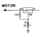
I want to provide a tape motor with 1.42v 60mA from a 13.5v source, without using a switching regulator. The problem is that the lm317 I use gets heated very quickly. Is there any way I can do it? maybe multiple step down regulators in series??
 

since you want 1.42 V at 60 mA from a 13.5 V source, you will have (13.5 V - 1.42 V) * 60 mA = 0.725 W (minimum)
to dissipate in any linear regulation scheme. the best you can do with linear regulators is to spread that energy across
multiple components, either by using external pass transistor(s), or by using a few lm317 (or similar) in series.

you could do this in two steps
first, a switching regulator to about 3 or 3.3 V (likely commercially available, as 3 and 3.3 are standard voltages)
second, the lm317 linear regulator (which is now about 1.5 V at 60 mA, or 90 mW)

you have not said why you don't want to use a switching regulator.
worst case, you'll have to add a few components to any control IC and a power resistor to provide a minimum load
 
Last edited:

The total power dissipation of a linear regulated power supply is (13.5-1.42)V * 0.06A = 0.72 W, independent of the number of used regulator devices. The overtemperature however depends on the available heat sinking.

TO220 package has 50 K/W junction to ambient thermal resistance without heat sink, achieving a well acceptable overtemperature of 36 K, where's the problem?
 

Heat dissipation will be approx 750mW across the regulator irrespective
of number of stages. Only adv is heat is divided in many stages
of regulation. Post the circuit schematic of your designed lm317regulator.
 

Heat dissipation will be approx 750mW across the regulator irrespective
of number of stages. Only adv is heat is divided in many stages
of regulation. Post the circuit schematic of your designed lm317regulator.

Here it is. The regulator gets very hot after a while, it should not because only 60mA is drawn!
 

Attachments

  • Capture.JPG
    Capture.JPG
    10.5 KB · Views: 149

Hi,

, it should not because only 60mA is drawn!
Current alone does not generate heat.
Power is what counts. And it is 750mW ..... and 750mW can be hot.

And as the others mentioned: there is no way around the 750mW as long as you insist on a linear regulator.
Thus the only solution is to spread the heat

Klaus
 

your resistor divider for the feedback is maximum of 120 ohm
since the output is 1.42 V, that's another 1.42/120 A = 12 mA draw

so the actual current through your regulator is not 60 mA, it's 72 mA
(13.5 V - 1.42 V) * 72 mA = 0.870 W (minimum)

so either do it in 3 or 4 stages, or use one switching regulator then one linear regulator
 

How about a power resistor divider prior to the regulator. Ok wire resistors, but they won't need heatsinking and are of less size than the heatsink when the regulator is used alone.
What values should I use roughly?
 

Hi,

Pass the heat to a transistor around the LM317. Described as High Current Adjustable Regulator, schematic at the bottom of the linked page.

Quite bad suggestion to 'avoid' an SMPS that may not work too well: chop up the 13V with a 555 astable and FET or BJT pass device +smoothing/hold-up capacitors at output before the LM317 to average e.g. 5V out - but no pwm control loop back into the 555 would make Vout unpredictable, maybe. And perhaps Iout may not be sufficient. Lots of 555 pwm circuits to look at, one SMPS with 555 in a Phillips or Signetics application note.

- - - Updated - - -

Calculate desired Vout + dropout voltage at required current + a bit more for ground pin current and motor start/stop draw across top resistor.

I do not want switching regulators placed inside my LF/HF transceiver.
How about some voltage drop diodes in series or a power resistor divider prior to the regulator?
 

No idea of LM317 dropout voltage. If less than 1.5V...

+-3V out if divider @ 200mA:

R1 = 50
R2 = 14

14/64 = 0.218
0.218 * 13.5V = +-2.95V.

Waste of battery capacity burning off power as heat constantly, imho.
 

You don’t want a divider in front of the regulator you want a single resistor in series with the input. Leave the input bypass caps right at the regulator input. Size the resistor to drop half the voltage (or so) at 60ma and it should help (it’s also good for noise and short circuit current limiting).
 

I have sometimes seen "current recycling" schemes in
which one function which wants a lot of current, is placed
"above" another which takes less such that the same
(or significant portion of) func1's through-current is
supplying func2. The voltage drop across f1 would happen
regardless, so turn it into a bonus. The job then would
be to ensure that the current -not- taken by func2 is
sunk, somehow, and that the minimum line voltage
can still accommodate the two functions' headroom
requirements.

60mA could perhaps be within the range of a (boosted)
shunt reference. If there are other "quiet" supplies of
lower voltage already made, then a series resistor /
shunt regulator could be a play. Of course you would
just be throwing those milliamps onto a different "heat
victim". But perhaps one already well wrung out and
heat-sinked.

Switching supplies don't -have- to be a radio-killer.
This may depend on frequency plan and where the
switcher noise / harmonics fall. Some topologies
are lower-noise than others. There are also now
products which combine switcher and LDO in a
single package.

A crude approach using a (say) zener-NPN pre-
regulator to knock down the voltage to (say) 5V
and then an adjustable series regulator to make it
1.42, would let you choose from many, many LDO
products at a much lower power dissipation there.
The NPN pass transistor can take a lot of heat and
you don't care about its thermal drift as it's not
responsible for output accuracy, just sucking up the
abuse.
 
  • Like
Reactions: d123

    d123

    Points: 2
    Helpful Answer Positive Rating
OR use one of these:
20200410_221123a.jpg
Cost almost nothing, runs almost cold at 3A load with no heat sink, fully adjustable output voltage between about 0.8V and > 20V and works from a supply of up to 28V.

Note: there is a PCB error on some of these modules, they have variable or present output at 1.8V, 3.3V, 5V, 9V and 12V but either the adjustment pot has to be set to max resistance or the track beside it needs cutting or the output will only adjust downward from the selected preset voltage.

**broken link removed**

Brian.
 

post show the image now.
please ignore any earlier message on image.
 
Last edited:

Status
Not open for further replies.

Similar threads

Part and Inventory Search

Welcome to EDABoard.com

Sponsor

Back
Top