Continue to Site

Welcome to EDAboard.com

Welcome to our site! EDAboard.com is an international Electronics Discussion Forum focused on EDA software, circuits, schematics, books, theory, papers, asic, pld, 8051, DSP, Network, RF, Analog Design, PCB, Service Manuals... and a whole lot more! To participate you need to register. Registration is free. Click here to register now.

[MOVED] Differences between 1port and 2port inductor

Status
Not open for further replies.

ahdzlqkdzl

Newbie
Joined
Jan 7, 2020
Messages
5
Helped
0
Reputation
0
Reaction score
0
Trophy points
1
Activity points
82
Hi, I'm new to design inductor in HFSS, also I use cadence for designing LNA.

and here is the question, when we use inductor for the matching circuit, do I have to use 1port single ended inductor?

or 2port differntial inductor?

there were differences between them. for example

1port(single ended) inductor spec: L= 172pH, Q=19.6, Fsr=122GHz
2port(differential) inductor spec: L= 152pH, Q=33.5, Fsr=221GHz

so, for the LC matching in LNA circuit, what kind of inductor do I have to use?

and I also found cadence provided RF inductor's finder value is about 1port single ended value.
 

Indeed, the calculated results are different for the same layout, as I explained in this appnote:
https://muehlhaus.com/support/ads-application-notes/inductor-em-ports

inductor_z1port.PNG

inductor_z2port.PNG

It depends on your use of the inductor which result is relevant for you. Often, the inductor is used in differential (symmetric) operation and then 1-port values for L and Q are fine.
 

thx for your replying! and your post was really helpful.

and I have one more question.
my circuit is not the differential circuit. using two terminal inductor without centertap.
and there are two kind of indurtor path.

so the
first is connected with Transistor one side and grounded the other side.

second is connected between two other circuit components.

but the inductor figures in your posting. it seemed like inductor for the differential circuit using differential signal.

my question is these,

1. those two kinds of inductors( first and second case) have to be called as single ended form?

2. and then, both two have to use one port analyzed value?

sorry for not understanding perfectly about your advicing n post. and I'm honored of your response.
 

Sorry, I misunderstood your question.

It is more complex: we have two different layouts (symmetric with center tap or non-symmetric single ended).

And in addition, the EM simulation model can be different: one port between the inductor terminals, or one port per inductor terminal (with all port references at substrate). That is what my appnote discusses. It is important to understand that your EM results will change depending on the port configuration. This is because every on-chip inductor has series (L,R) and shunt path (to substrate). My description in the appnote applies to both inductors, symmetric or non-symmetric.

Sorry I can't give a better description. You need to understand these effects, for proper use of ports, otherwise your EM results will be misleading.

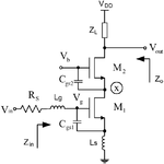
Inductively-degenerated-cascode-CS-LNA.png

thanks again for your replying.
yes you are right. my inductor type is non symmetric single ended inductor like the Lg in the LNA schematic circuit.

and my circuit doesn't use the differential or common mode. so fhe inductor I'm designing takes only one single input and output. also it doesn't have center tap.

and I used folmula Ldiff and Q diff using parameter (Z11+Z22-Z12-Z21) with 2port.
I thought this was my mistake. I should have used 1port L,Q formula using parameter Y11.

cause all those 2 port formula used in differential circuit only.
 

and I used folmula Ldiff and Q diff using parameter (Z11+Z22-Z12-Z21) with 2port.
I thought this was my mistake. I should have used 1port L,Q formula using parameter Y11.

If you use equation
Zdiff = Z(1,1) – Z(1,2) – Z(2,1) + Z(2,2)
on the 2-port simulation, you will get the same results as the 1-port simulation with port between both inductor terminals.

so the inductor I'm designing takes only one single input and output. also it doesn't have center tap.

Sure. But you need to understand that the 1-port data gives you only the (effective) series path. This data does not give information on the shunt path - every inductor has a shunt capacitance to the substrate, that is why I showed the equivalent circuit models.

So if you want to ingnore that shut capacitance in your circuit simulation, you can use 1-port EM simulation to get an effective Lseries and R series. If you want more accurate data, you better do a 2-port simulation and use the S2P data, or create a full equivalent circuit model from the 2-port data. For ADS, I have an automated to to create Spectre inductor models from 2-port data (S2P): https://muehlhaus.com/products/equivalent-circuit-model-fit-for-rfic-inductors
 
Last edited:
Status
Not open for further replies.

Part and Inventory Search

Welcome to EDABoard.com

Sponsor

Back
Top