Continue to Site

Welcome to EDAboard.com

Welcome to our site! EDAboard.com is an international Electronics Discussion Forum focused on EDA software, circuits, schematics, books, theory, papers, asic, pld, 8051, DSP, Network, RF, Analog Design, PCB, Service Manuals... and a whole lot more! To participate you need to register. Registration is free. Click here to register now.

Differential pair with dynamic resistance

Status
Not open for further replies.

DavidYebadlo

Junior Member level 1
Joined
Apr 6, 2020
Messages
17
Helped
0
Reputation
0
Reaction score
0
Trophy points
1
Activity points
177
Hi,
I need to calculate and draw asymptotes on the oscilloscope.
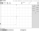
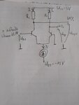
dyn20k_IE1_5mA.png
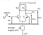
The tested system looks as follows:
zadanie.png
One change - Rc = 20k Ohms.
I know that for voltage Ub1 in range for +-0.1V (approximately) transistor T2 is in the active mode. And i notice that Uwy1 is constant and this voltage is 5V. So transistor T1 is in cut-off mode. But i don't know how T2 transistor works when Ub1 voltage is less than -0.1V and when Ub1 voltage is greater than 0.1V. Does it work in saturation mode? Could you explain me?
Thanks for the help in advance!
 

Basically 3Vt (≈80mV) is an input differential voltage range of a BJT diff pair (you can check math analysis in Grey, Hurst, Meyer book "Analysis and design...").
If Vin_diff is higher than this 3Vt value one guy is cut-off, while second is saturated.

However, If your Re is 2.5kΩ, Rc is 20kΩ, input common mode is on ground, VEE is -5.7V and VCC is 12V, then your amplifier is in trouble.
Only left guy might be in active-linear mode, right is always squeezed by large Rc resistor.
So, for input voltage below ground, output is going to be ca Vcc-(Vcc-Vee-Vcesat)Rc/(Rc+Re), while in opposite situation, output is pulled up by Rc to Vcc.

Also, your question is not fully clear. Attached scope screenshot is in time domain and I believe it is showing full range response.
So, asymptotes of what you need?
 

I forgot to mention that the system is powered by a current source IE = 1.5mA. And now I noticed that I sent the wrong layout. The following is correct:
zad.png
 

Okay, it's correct electronic circuit: 92412658_239485123912824_8536469142587310080_n.jpg
and it's my assumptions and calculations:
T1 is cut-off and T2 is saturated then output voltage Uwy2 is approximately -1V.
My calculation:
Ucc-Ic*Rc+UBC2=0
UBC2-voltage base-collector on transistor T2
UBC2=0.5V because UCE=UCEsat=0.2V and UBE=0.7V
Then Ic=0.275mA
Next Uwy2=UCC-Ic*Rc=-0.5V
Is it OK? My calculations do not differ much from the oscilloscope, but I don't know if I do it correctly...
 

You new schematic doesn't even give a value for Rc. How could we answer?

As previously mentioned, saturation occurs above a certain value of Rc. Usually, saturation would be avoided. But it's not clear waht you want to achieve.
 

Status
Not open for further replies.

Part and Inventory Search

Welcome to EDABoard.com

Sponsor

Back
Top