carpenter
Full Member level 6
I pardon myself in advance for a partially philosophical question.
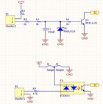
Have me any device powered with 230V to 24DC and 5V DC , for standard home and office safety level, ground of device is connected to PE. In device is MCU and any digital input, we need to take them out of the device for general use, for example foot switch, for driving device with any PLC , etc.
I always wonder how to reliably implement such an input?
Any as on in the picture above or in the bottom or the other way?
