shanmei
Advanced Member level 1
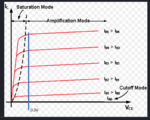
The bipolar active linear (amplification) region is defined as Vbe>0 and Vbc<0, and the saturation region is defined as Vbe>0, and Vbc>0. Note that this is bipolar, the saturation region of bipolar with similar with the linear region of cmos.
In my simulation, Vbe=0.75V, I sweep the Vce from 0 to 2V, and I found that the collector current becomes almost constant when Vce is larger than 0.3V. We can say that when Vce is larger than 0.3V, BJT is in active linear region.
The confusion is that in definition, for the active linear region, the definition requires Vbc<0. However, in my simulation, Vbc=0.7-0.3=0.4V >0, and BJT enters the active linear region. Why? Can you please explain?
