Continue to Site

Welcome to EDAboard.com

Welcome to our site! EDAboard.com is an international Electronics Discussion Forum focused on EDA software, circuits, schematics, books, theory, papers, asic, pld, 8051, DSP, Network, RF, Analog Design, PCB, Service Manuals... and a whole lot more! To participate you need to register. Registration is free. Click here to register now.

Efficiency of four fed patch antenna

Status
Not open for further replies.

slazen

Newbie
Joined
Feb 27, 2009
Messages
2
Helped
0
Reputation
0
Reaction score
0
Trophy points
1,281
Activity points
1,357
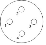
There is four fed patch for circular pol (see Attachments) simulated in CST. When 1 port is excited the S31 is about -4dB, S21=S41=-13dB, S11=-15dB. It means that total efficiency of antenna is less than 60%, because ~40% of power return to the port 3. When all ports simultaneous excitation are performed the efficiency more than 95%.
Why efficiency calc doesn't connected with S-parameters? Do you have some articles or books about the problem? Thanks.
 

Attachments

  • 4 patch.jpg
    4 patch.jpg
    7.7 KB · Views: 143

I will start by saying that your numbers sounds too bad. Coupling mechanisms for such structures are: radiation and due to surface waves, however in a passable design results should be much better.
May I ask what is the distance between the patches and GND? Is your design optimal?

Radiation efficiency is defined by the amount of power that is radiated divided by the acceptable power, where the acceptable power is the difference between the input power and reflected power.
The reason behind this 'weird' definition is that when you design an antenna you can separate between two causes:
a. Antenna matching.
b. How good my antenna acts like an antenna - efficiency.
 

When all ports simultaneous excitation are performed the efficiency more than 95%.

My explanation: For simultaneous excitation, the transmission from 1 to 3 looks like port 3 reflection to the software. Then it is not "loss" for an efficiency calculation.

Why do you have 4 feeds instead of 2?
 
My explanation: For simultaneous excitation, the transmission from 1 to 3 looks like port 3 reflection to the software. Then it is not "loss" for an efficiency calculation.

Why do you have 4 feeds instead of 2?

I Agree with your comments. I related to radiation efficiency for a single port antenna, which is not the case here.
 

4 feeds is use to obtain good axial ratio, phase center stability, rad. pattern in hemisphere, because it is GNSS antenna (f1~1230 MHz, f2=1560 MHz). Below the power and efficiency vs frequency is presented.
1 port is excited:
1 port.jpg
1 port effi.jpg

4 ports are excited:
4 ports.jpg
4 ports effi.jpg

«power outgoing all ports» contains reflected and transmited to other port power.
An efficiency calculation takes «power outgoing all ports» into account
powers model.jpg

Calculation was performed by combining 3d farfield, but when real devider was used in model, the efficiency results have been the same.
 

4 feeds is use to obtain good axial ratio, phase center stability, rad. pattern in hemisphere, because it is GNSS antenna (f1~1230 MHz, f2=1560 MHz). Below the power and efficiency vs frequency is presented.
1 port is excited:
View attachment 158314
View attachment 158315

4 ports are excited:
View attachment 158316
View attachment 158317

«power outgoing all ports» contains reflected and transmited to other port power.
An efficiency calculation takes «power outgoing all ports» into account
View attachment 158318

Calculation was performed by combining 3d farfield, but when real devider was used in model, the efficiency results have been the same.
Gain charts?
 

Hi slazen,

I have designed and validated a dual-band, quad-feed circular patch antenna for GPS L1 and L2 before, and I've seen this as well. What you're looking at is most likely the case where the circular patch is resonating in a linear-type mode; that is, if you look at the fields you should expect to see a standing wave consisting two-half circles, each with opposite phase, as you would in a typical rectangular patch.

This is because the definition of scattering parameters requires that only the one port be excited, while the others are matched, so of course you wont's see circular polarization. Since ports 2 and 4 are along the null line of this resonance, not much power couples out of them. However, since port 3 is on the far side, it is at a field maximum and therefore a fair amount of power will couple out of it.

This is normal operation of the antenna; as pointed out here there is no issue with efficiency -- in normal operation you'd want to be exciting all ports, which is not what the scattering parameters reflect.
 

Status
Not open for further replies.

Part and Inventory Search

Welcome to EDABoard.com

Sponsor

Back
Top