Continue to Site

Welcome to EDAboard.com

Welcome to our site! EDAboard.com is an international Electronics Discussion Forum focused on EDA software, circuits, schematics, books, theory, papers, asic, pld, 8051, DSP, Network, RF, Analog Design, PCB, Service Manuals... and a whole lot more! To participate you need to register. Registration is free. Click here to register now.

Please Help to avoid short circuit when operating a PWM rectifier ?

Status
Not open for further replies.

javo86

Newbie level 2
Joined
Dec 5, 2018
Messages
2
Helped
0
Reputation
0
Reaction score
0
Trophy points
1
Activity points
27
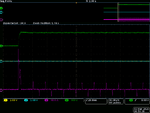
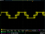
Hey guys, I will appreciate if you can give an advice, please, I'm currently developing a single phase active front end rectifier but I'm facing some issues, I have the power stage which is an H bridge with a fuse and inductor for couplig, but first I tried to operate it in open loop as inverter with a DC source and It worked fine, then I connect it to the AC grid and operated it as rectifier (using the parasitic diodes) and also works ok, rectifying de AC side and charging the capacitor and also I can see the distorded current as you can see in the attached figures. Now I'm stuck in the next step, when operating it as a PWM rectifier (in open loop), in order to avoid the high current at the beginning, I first rectify the AC voltage to charge the capacitors but when I apply the pulses the fuse always blow and the AC breaker trips. I've double check the board and there's no short circut between paths...I also attach the schematic of the converter. I'm using a 3.3 mH inductor for coupling to AC side and Im generating the pulses with a single-board rio (Labview), I'm using unipolar PWM modulation strategy (two sinusoidal modulating signals) cause I will be using dq control. I have also developed the dq controller but first I want to try it in open loop with any luck. I don't know if there's a consideration that I shoul be taking into account in order to operat it as a PWM rectifier?
 

Attachments

  • AFER.png
    AFER.png
    22.3 KB · Views: 83
  • tek00018.png
    tek00018.png
    26.4 KB · Views: 80
  • tek00008.png
    tek00008.png
    62.6 KB · Views: 80

Hi,

I don't know about that kind of circuit, so my answer is not much use. It sounds like you've checked that there is no inrush current but fuses blowing and circuit breaker tripping sound like an over current event. Does the circuit you are making use soft start circuitry or zero crossing detector circuitry? I don't see anything like that in the schematic that I can identify.

- - - Updated - - -

Or maybe the FETs need dead time if not already incorporated and circuit gets a shoot-through moment through two switches that have overlapping on-time or something.
 
  • Like
Reactions: javo86

    javo86

    Points: 2
    Helpful Answer Positive Rating
Thanks for your reply, actually I´m also generating the dead time, but I forgot to mention that the MOSFETs are blowing too. Maybe is the PWM pattern but I've already checked the dead time and the correct PWM pattern for each MOSFET in the scope... I'll try with the soft starter circuitry, do you know any circuit, please?
 

Hi,

I do very, very simple things like soft start transistors with resistors and capacitors on the gate, not sure how to fit that into your circuit. But coincidentally for inrush control topic, I was reviewing 1 Ohm resistors I have to select one I need to use for current sensing today and re-read Vishay ACxx wirewound series documents which say they can be used for inrush current-limiting and double up as a fuse. Pdf pamphlet attached to get an idea of that kind of resistor. Sorry can't be of more help.

View attachment 0900766b81728451.pdf

- - - Updated - - -

Looking at the 10A spike + 100V, is it possible start-up surpasses NMOS PD for too long, SOA graph defined, or they need more heatsinking? Mosfet pair blow for whatever reason, then short circuit happens, which leads to fuse blowing last? I guess they turn on quickly to minimise vds? Can you turn on first pair slowly then return to PWM pattern or is that not possible? I'm out of my depth here, to be honest.
 

I don't understand what you mean with "open loop" operation when the inverter is connected to the grid? The modulation must be applied with exactly correct magnitude and phase, otherwise you get high currents. The first waveform shows overmodulation and no clean sine.

To start the circuit without immediately blowing the fuse, you can connect a current limiting resistor.
 

Status
Not open for further replies.

Part and Inventory Search

Welcome to EDABoard.com

Sponsor

Back
Top