javo86
Newbie level 2
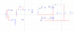
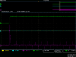
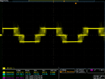
Hey guys, I will appreciate if you can give an advice, please, I'm currently developing a single phase active front end rectifier but I'm facing some issues, I have the power stage which is an H bridge with a fuse and inductor for couplig, but first I tried to operate it in open loop as inverter with a DC source and It worked fine, then I connect it to the AC grid and operated it as rectifier (using the parasitic diodes) and also works ok, rectifying de AC side and charging the capacitor and also I can see the distorded current as you can see in the attached figures. Now I'm stuck in the next step, when operating it as a PWM rectifier (in open loop), in order to avoid the high current at the beginning, I first rectify the AC voltage to charge the capacitors but when I apply the pulses the fuse always blow and the AC breaker trips. I've double check the board and there's no short circut between paths...I also attach the schematic of the converter. I'm using a 3.3 mH inductor for coupling to AC side and Im generating the pulses with a single-board rio (Labview), I'm using unipolar PWM modulation strategy (two sinusoidal modulating signals) cause I will be using dq control. I have also developed the dq controller but first I want to try it in open loop with any luck. I don't know if there's a consideration that I shoul be taking into account in order to operat it as a PWM rectifier?