Continue to Site

Welcome to EDAboard.com

Welcome to our site! EDAboard.com is an international Electronics Discussion Forum focused on EDA software, circuits, schematics, books, theory, papers, asic, pld, 8051, DSP, Network, RF, Analog Design, PCB, Service Manuals... and a whole lot more! To participate you need to register. Registration is free. Click here to register now.

switch-capacitor noise -psd

Status
Not open for further replies.

akbarza

Full Member level 2
Joined
Dec 18, 2013
Messages
131
Helped
0
Reputation
0
Reaction score
0
Trophy points
1,296
Activity points
2,556
Hi
in file switch-capacitor circuits from Prof. Y.Chiu -data converters eect 7327 in slide 25,
he has said that Total integrated noise power remains constant( pic: niose.png).
but i think because of aliasing in sampling the
noise is aggressive of some noise spectrum as I drawn in alias.png.( i drew pic in paint, if is bad excuse me)
so because noise is random in phase, the sum tend to zero and PSD(power spectral density) of sample noise must be approximately zero. this is my
explanation: for switch capacitor circuit(with two phase ph_1 and ph_2) , some noise in ph_1 is created and then this noise with input signal in ph_2 is sampled. i think with this sampling,the created noise in ph_1 is eliminated(for withe noise because of infinite bandwidth ). but in ph_2, new noise is created by switches that remains and appears in output.
this is my opinion. am i wrong?

please explain and thanks.
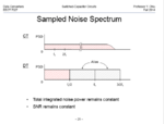
noise.png
ALIAS.png
 

Noise is random and its average value is 0 but the power is not. Hence, PSD or noise power per unit frequency is finite. PSD of sampled noise is same as the PSD of the continuous time noise process from which the samples were taken.
In switched capacitor circuites both ph1 and ph2 contribute noise to the output, say at the end of ph2.

hi and thanks for answer
with attention to below pic( after sampling), input signal spectrum( in this place , white noise) is shifted with many multiples as 2fs.
so for example for a special frequency as f0, sampling create new frequency as f0+2fs, f0+4fs, f0+6fs,... with their own phase.
we notice that we work with white noise that has large extend in frequency domain. so many number of frequency with their own phase shifted to special frequency.
the sum of these frequencies is used for determine of psd in the this special frequency.
i hope to could my meaning
 

It is probably true that if you look at the output noise of a S/H in continuous time it will be some sinc shaped spectrum. But why do you need that? It is a sample and hold and we are interested in the noise only at discrete points of time. That is
we have discrete noise samples and their spectrum is only in 0 to Fs/2 frequency range. We know that the variance of that sequence of noise samples i.e. the noise power is equal to the variance of the continuous noise process before the sampler, which means it is proportional to kT/C. If the S/H time constant is small compared to the time interval during which the switch is closed, then the noise in 0 to Fs/2 is pretty much white. And its PSD is defined by how many frequency sidebands are folded over into 0 to Fs/2.

hi sutapanaki
I read your explenation but i don't understand.
you say:we have discrete noise samples and their spectrum is only in 0 to Fs/2 frequency range. I think we have after ph_1 a white noise.can explain your opinion?
you say:We know that the variance of that sequence of noise samples i.e. the noise power is equal to the variance of the continuous noise process before the sampler, which means it is proportional to kT/C. please introduce a reference for this. i can not approve it.
is below explenation right?
In ph1, KT/C noise is created( as you know the KT/C noise is sum or integral of noise spectral for white noise) . so i can say after ph_1 i have noise on across C capacitor with total value as KT/C.
In ph_2 , this broadband noise is sampled as the vin in across c is sampled. so with f0 frequency sampling, this noise is sampled and folded. these folded parts of principle spectrum of noise are added together so the contribution of KT/C is approximately zero after ending of ph_2.
thanks for reply

i am not english native,so excuse me if i can not declare clearly my meaning.
 
Last edited:

Hi,

I read your explenation but i don't understand.
you say:we have discrete noise samples and their spectrum is only in 0 to Fs/2 frequency range. I think we have after ph_1 a white noise.can explain your opinion?
Fs/2 simply is according Nyquist and should be clear.

And for me it makes sense not to do a continous noise analysis. Usually after the S/H there is an ADC...and the S/H voltage level and noise during sampling, during switching and close to switching is not of interest. Only the steady state in hold phase is of intereset. This is where the ADC generates the conversion.

Klaus
 

hi sutapanaki
I read your explenation but i don't understand.
you say:we have discrete noise samples and their spectrum is only in 0 to Fs/2 frequency range. I think we have after ph_1 a white noise.can explain your opinion?
you say:We know that the variance of that sequence of noise samples i.e. the noise power is equal to the variance of the continuous noise process before the sampler, which means it is proportional to kT/C. please introduce a reference for this. i can not approve it.
is below explenation right?
In ph1, KT/C noise is created( as you know the KT/C noise is sum or integral of noise spectral for white noise) . so i can say after ph_1 i have noise on across C capacitor with total value as KT/C.
In ph_2 , this broadband noise is sampled as the vin in across c is sampled. so with f0 frequency sampling, this noise is sampled and folded. these folded parts of principle spectrum of noise are added together so the contribution of KT/C is approximately zero after ending of ph_2.
thanks for reply

i am not english native,so excuse me if i can not declare clearly my meaning.

You have to try and imagine what happens in ph1 and ph2 of a S/H or in fact any switched capacitor circuit. In ph1 we track the input and then sample it at the end of ph1. Then, in ph2 the rest of the switched capacitor circuit grabs that sample and process it and produces the output at the end of ph2. So, from the point of view of the output and ph2, the circuit is really working with samples, not continuous time process i.e. it is a discrete signal processing. With respect to noise at the input - yes, there we have continuous time noise process, and when the input switch is closed during ph1, that continuous noise reaches the sampling cap but the moment we open the sampling switch we freeze a noise sample over the sampling cap. Or rather, we freeze noise charge sample. In ph2 that sample is transferred and redistributed to output cap. CT noise during ph2, from switches, amplifier, etc also gets sampled at the end of ph2.
Every time we sample a signal and take discrete points of that signal, like what ADC does when it converts the output of a S/H circuit, we work only in the frequency range from 0 to Fs/2 (Fs is the sampling frequency). This just comes from the periodic nature of discrete sine signals or complex exponentials. If a signal extends beyond Fs/2 it will alias back into that first Nyquist range (0 to Fs/2). In the case of noise, it is going to high frequencies, defined by the cut off of the input sampling R and C, but then upon sampling folds down into 0 to Fs/2 range. Parseval's theorem says that the power of signal in time domain is equal to the integral over all frequencies of its PSD. Also, in case of noise, it is an ergodic random process with 0 mean and then if we take samples of that process, basically just sequence of random numbers, the variance should be the same as if we had multiple realizations of the process and we sampled all of them at the same point in time and collected ensemble samples - these have the same variance. Variance is in fact power of noise. So, as a consequence, whatever is the power of the continuous time noise process, such is the power of the samples we take from that process. The continuous process has variance which is kT/C, and the discrete noise process also has variance that's kT/C. In the continuous case the kT/C is distributed in frequency from 0 to the noise BW of the circuit, something like 1/4RC. Because of aliasing, in discrete time that same kT/C power is distributed in 0 to Fs/2 because that's the only frequency range that exists in discrete time. But the spectrum of discrete noise is still white, which means uniform in that range, provided that withing the time period of 2/Fs we can fit more than 3 or 4 time-constants of the sampling network, which usually is the case in all practical circuits.
 
Last edited:
thanks sutapanaki
i want to know more about this subject. can you introduce a reference to me?
thanks again
 

Status
Not open for further replies.

Part and Inventory Search

Welcome to EDABoard.com

Sponsor

Back
Top