Continue to Site

Welcome to EDAboard.com

Welcome to our site! EDAboard.com is an international Electronics Discussion Forum focused on EDA software, circuits, schematics, books, theory, papers, asic, pld, 8051, DSP, Network, RF, Analog Design, PCB, Service Manuals... and a whole lot more! To participate you need to register. Registration is free. Click here to register now.

LM567 morse code detector weird thing

Status
Not open for further replies.

neazoi

Advanced Member level 6
Joined
Jan 5, 2008
Messages
4,122
Helped
13
Reputation
26
Reaction score
15
Trophy points
1,318
Location
Greece
Activity points
36,951
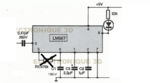
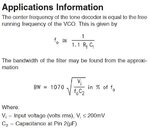
Hi I have made a tone detector using the LM567. at pins 5 and 6 a variable resistor should be connected to select the frequency. However I have found that when I do so the only setting that detects tones is the short (i.e pins 5 and 6 shorted. There is a 100nF from pin 6 to GND.
I also have a variable narrow AF filter prior to the LM567. When I set this filter at whatever frequency I want and by feeding the peak frequency tone to it, The LM567 detects that tone ok as long as the input volume to it is at a certain level. It is like the potentiometer between pins 5 and 6 is not needed.
Is that normal?
 

It so happens I built my own morse code detector similar to yours. The 567 IC is simple to use and works well if you feed it a waveform close to its center frequency and within the required volt range.

The RC network determines the center frequency and the bandwidth. Perhaps you chose a C value which matches your desired frequency. However I think with further experimentation you'll find a resistor (or potentiometer) lets you fine-tune the bandwidth. A narrow bandwidth is needed in order to minimize false responses to rogue beeps off-frequency.
 
  • Like
Reactions: neazoi

    neazoi

    Points: 2
    Helpful Answer Positive Rating
You can tune the VCO center frequency to the intended detector frequency without input signal. Observe it at pin 5 with an oscilloscope. Or calculate R and C values according to the datasheet f0 formula at page 8.

Post #1 suggests that something is completely wrong in your setup.

But it works fine. It detects tones and on tone it switches off the led (vcc-to-zero-pulse).
This is the setup:
pin 2 to gnd, 1uf
pin 1 to gnd, 2.2uf
pin 6 to gnd, 100nf
pin 5 shorted to pin 6

a 22k variable resistor from pin 6 to pin 5 was working ok only at it's lowest resistance.

The weird thing is that the chip detects ANY tone frequency. The variable peak narrow audio BPF I have before the 567, takes care well of the frequency selection.
The input tone level needs to be adjusted within a min-max range for the chip to detect tones ok.

Why is this setup working were it shouldn't?
 

Generally the Morse code CW pitch frequency is about 600Hz. The variable resistor between pins 5 and 6 is part of the RC network that gives the decoded frequency, and is almost impossible to be short (0 ohms) for this frequency.
By definition of its role, LM567 don't need any filter in front of it. The capacitor to the ground on pin 2 gives the bandwidth of the circuit.
Otherwise the best Morse code filter that I ever use, is my brain.

You are right, even if I switch off the narrow filter and increase a bit the volume to the 567, it still decodes, provided that there is no other tone within the passband.

I don't know, it just works in my case with the values described, and it is broadband, detecting any frequency...
 

it just works in my case with the values described, and it is broadband, detecting any frequency...

I'm sorry to disappoint you, but if is detecting any frequency, means that doesn't work.
 

I'm sorry to disappoint you, but if is detecting any frequency, means that doesn't work.

Well it does, as a detector. In fact it is more convenient that way as I do not have to tune the 567 along with the af filter. At whatever frequency I tune the filter, it's this frequency that is detected by the 567.
However, I wonder why it does this way.
Anyway, it turns out there is no answer.
 

Neazoi;

You are a very experienced and helpful EDAboard member.

You know that to obtain meaningful help, the more information one provides, the better. A schematic diagram, photos of the circuit, waveforms, voltage readings, etc.
 

Neazoi;

You are a very experienced and helpful EDAboard member.

You know that to obtain meaningful help, the more information one provides, the better. A schematic diagram, photos of the circuit, waveforms, voltage readings, etc.

Ok it is this one. (edited with paint) the deleted pot is shorted, so pins 5 and 6 are shorted.
 

Attachments

  • 22.png
    22.png
    124.2 KB · Views: 307

According to the LM567 datasheet application note, to get a detected frequency fo = 600Hz (CW pitch) R1 should be 15k and C1 = 100nF (which it is).
With C2 = 1uF the detector Bandwidth is 20%, which should be fine.
If you cannot set R1 to about 15k to decode 600Hz, means that LM567 is dead, or the passive components you use are not good.
 

Attachments

  • LM567.jpg
    LM567.jpg
    35.9 KB · Views: 273
  • Like
Reactions: FvM

    FvM

    Points: 2
    Helpful Answer Positive Rating
According to the LM567 datasheet application note, to get a detected frequency fo = 600Hz (CW pitch) R1 should be 15k and C1 = 100nF (which it is).
With C2 = 1uF the detector Bandwidth is 20%, which should be fine.
If you cannot set R1 to about 15k to decode 600Hz, means that LM567 is dead, or the passive components you use are not good.

It was a dead LM567....
 

Your narrow-band-pass filter may be sufficient, without needing the 567 IC.
Rectify the waveform to become DC pulses. Then attach a smoothing capacitor. Then an invert-gate buffer.

The filter passes a few cycles at a time(dot, dash, whichever). As a result the final output changes state briefly. I believe that substitutes for the function of the 567.

Yes something like the attached version. BTW in this version he mentions that the output of the BPF is a modulated AM audio which he then recovers to baseband audio. This is confusing, what does it mean?
 

Attachments

  • QRM fighter for CW.pdf
    19.5 MB · Views: 174

The circuit is basically a gated audio oscillator. The gate is turned ON and OFF by the envelope detector (U3) of the received signal.
When you tune your receiver to a CW (Morse code) signal, actually you don't hear the real tone of the CW signal, but you hear the local audio oscillator (U4) which is triggered by the signal.
It will work for sure, I've seen something similar implemented in a digital signal processor (DSP).

The issue of this approach is for a real Morse code fan, who like to hear the chirp, the melody, of the CW signal, and not a local "robot" inside of the receiver.
Anyway, this circuit it will work only with relative strong received signals, for weak CW signals with low SNR only ear-and-brain can help.
 

Attachments

  • Weak_Signal_SNR_Limits.jpg
    Weak_Signal_SNR_Limits.jpg
    22.4 KB · Views: 138
  • Like
Reactions: neazoi

    neazoi

    Points: 2
    Helpful Answer Positive Rating
I concur. All it does is replace the incoming signal with a 'clean' one generated in the unit. It may sound nicer but it won't help much in a pile up.

The difference between the two methods is one is an envelope detector, the other is a frequency detector. The LM567 works on the frequency detecting principle, it 'free runs' an oscillator at the pitch you want to detect and attempts to phase lock it with the incoming signal. The bandwidth you choose decides how close the incoming frequency is before it can be 'grabbed' to achieve the lock and it is whether the lock was successful or not that gives you the recovered Morse code.

Brian.

What I like in the QRM fighter is the delay network, which removes spikes and noises so as not to be heard on the audio tone generated. This delay or a similar feature is achieved with capacitors in the 567 case. If you make the caps 100nf and 220nf for example, the led detects noise as well.
On the other hand the 567 is more sensitive and I guess more selective without so many extra components used. There is no bandwidth or band center in the 567 case. I think I am going to use this part.
All that remains is an adjustable sine AF oscillator that can be triggered on 1 to zero transition out of the 567. Any ideas?
 

All that remains is an adjustable sine AF oscillator that can be triggered on 1 to zero transition out of the 567. Any ideas?
You want it enabled or gated by the output of the PLL lock signal, not triggered by the transition. Use any audio oscillator you want, it is just creating the tone you hear so it can be anything from a 555 to a pure sine according to your preference.

Note that the NE567 has an unusual characteristic that it's bandwidth varies with input level. It will lock over a wider bandwidth when the input signal is larger so for best results keep the input signal as small as practical. You will probably have to experiment to find the best level or maybe fit a pre-set pot at its input to make it adjustable.

Brian.
 
  • Like
Reactions: neazoi

    neazoi

    Points: 2
    Helpful Answer Positive Rating
You want it enabled or gated by the output of the PLL lock signal, not triggered by the transition. Use any audio oscillator you want, it is just creating the tone you hear so it can be anything from a 555 to a pure sine according to your preference.

Ok so just use a transistor (or a pair ones for reverse operation) to enable the power to this oscillator? Or maybe shunt the audio of the oscillator to ground. How about this oscillator https://learnabout-electronics.org/Oscillators/osc34.php which by the way I would like to convert it to use single rail supplu (13.5v available) but I do not know how

Note that the NE567 has an unusual characteristic that it's bandwidth varies with input level. It will lock over a wider bandwidth when the input signal is larger so for best results keep the input signal as small as practical. You will probably have to experiment to find the best level or maybe fit a pre-set pot at its input to make it adjustable.
Brian.

I have found that experimentally, yes. The most "selective" point is the lowest volume one that allows lock. Higher volumes are acceptable up to a point if there is only one signal, but care must be taken so that the 567 does not detect noise at these levels. As you know, keeping the level stable on HF is not a trivial task with non-dsp circuits, with all this fading of the signals. An AGC would try to do that, but on low signal levels it will try to increase the noise as well, so no good for the 567.
 
Last edited:

There are many ways to do it. All of your methods will work. Possibly the easiest is to use a a CD4016/CD4066 and gate the tone from the NE567's own oscillator using it's lock detect output. If you use one of those, remember that you can use one of the four signal gates as a logic inverter to turn the active low output froom the 567 to an active high to control another signal gate. Also remember that the 567 has an open-collector output so it needs a pull-up resistor to achieve logic high state.

I would suggest that to limit the input signal level you use a 10K resistor then two Schottky signal diodes in parallel across the signal. As it is frequency sensitive, as long as you keep the input level reasonably low , it will ignore the actual volume level.

There are many alternative solutions, for example you can use some DTMF tone detectors in single tone mode and they already have built in filters or you can use FM stereo decoders by lowering their normal 19KHz pilot tone filter components and using the stereo/mono output or of course many other types of generic PLL.

Brian.
 

Status
Not open for further replies.

Part and Inventory Search

Welcome to EDABoard.com

Sponsor

Back
Top