Continue to Site

Welcome to EDAboard.com

Welcome to our site! EDAboard.com is an international Electronics Discussion Forum focused on EDA software, circuits, schematics, books, theory, papers, asic, pld, 8051, DSP, Network, RF, Analog Design, PCB, Service Manuals... and a whole lot more! To participate you need to register. Registration is free. Click here to register now.

Remote Controlled Switch Board Issue

Status
Not open for further replies.

baileychic

Advanced Member level 3
Joined
Aug 2, 2017
Messages
728
Helped
56
Reputation
112
Reaction score
57
Trophy points
28
Activity points
7,033
Remote Controlled Switch Board Issue

See attached circuit.

This is the circuit which I designed.

The issue is there is no common GND between VSINE (220V Neutral) and 5V circuit GND.

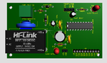
I am using Hi-Link 5V 3W SMPS module to get power for circuit.

Will the ZCD circuit work?

I want to turn On/Off SSRs at ZC and so I have used the ZCD circuit. ZCD circuit input is from LINE.

In simulation if I connect NEUTRAL to chassis connector (I guess GND and Chassis are both 0V in Proteus) then circuit works but in real hardware connecting NEUTRAL to 5V circuit GND is wrong.
 

Attachments

  • RCSB-1.PDF
    36 KB · Views: 109

Hi,

Simplest solution: there are many SSRs with ZC switching included.

Klaus
 

Attachments

  • RCSB-3DV-1.png
    RCSB-3DV-1.png
    117.8 KB · Views: 110
  • RCSB-SCH.PDF
    36 KB · Views: 97
  • RCSB-PCB.PDF
    320.4 KB · Views: 119

If your SSR is the 'P' version but not one with another letter after the 'P' you can forget the ZC altogether.

Not connected directly with this but worth mentioning: many of the multi-relay boards sold on Ebay that use opto-isolators are NOT actually isolated. For some bizarre reason, all the optocoupler supplies are joined together and their outputs drive transistors that also have all their emitters joined together. In other words the optocoupler does nothing useful at all. I use them because they are cheaper than building my own but I remove the PC817 and link across it's input to output pads on the PCB.

Brian.
 

It is exactly Omron G3MB-202P

My Robu.in relay board doesn't have opto-isolator but why that is needed when the internal of the SSRs are already opto-isolated?
 

Status
Not open for further replies.

Similar threads

Part and Inventory Search

Welcome to EDABoard.com

Sponsor

Back
Top