Continue to Site

Welcome to EDAboard.com

Welcome to our site! EDAboard.com is an international Electronics Discussion Forum focused on EDA software, circuits, schematics, books, theory, papers, asic, pld, 8051, DSP, Network, RF, Analog Design, PCB, Service Manuals... and a whole lot more! To participate you need to register. Registration is free. Click here to register now.

How D flip flop can hold output until next clock cycle when it is level firered.

Status
Not open for further replies.

miso156

Junior Member level 2
Joined
Jan 13, 2019
Messages
23
Helped
0
Reputation
0
Reaction score
0
Trophy points
1
Activity points
222
Hello All,

I need to design a clock devider using PBJT. So it should look like this:
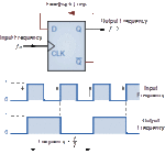
counter-cou1.gif

However, when i do it from PBJT, the output starts oscilate due to immediate changes of D input, when clock is high.

5c986870c672e02269085a28.jpg

Id like to build this to hold the output until next positive level of CLK come. Maybe it will be necessary to use another SR flop, or some logic, i dont care, but do not to use edge triggering.
 

This sure looks like homework...

Look over you notes, I'm sure they instructor must have discussed master-slave d-flip flops. Use google and find information on the circuit that implements that.
 
  • Like
Reactions: d123

    d123

    Points: 2
    Helpful Answer Positive Rating
Its not homework, I am bit older.

I m trying to do it like fig. below, so the 1st Dflop can become lock, and i need to open it in every second clock by 2nd Dflop. Of course it isnt working, I need to help with this. It probably would be neede to sense a negative clock pulse also and make the conditions. Its very similar to circuits "turn on-off by one button".

Be.png
 

Hi,

CD4013 datasheet by TI has a momentary on/off schematic in the typical applications section. Parsing the truth table, or deciphering it in my case, shows many combinations possible for different outputs and reset events.
 

you need to understand the difference between latch and flop, level and edge.
 
  • Like
Reactions: d123

    d123

    Points: 2
    Helpful Answer Positive Rating
Specifically, you (OP) show first a flip-flop in toggle
feedback configuration, but then you show a half-
latch (half of a D FF) in the same feedback config
and expect it to work the same (it won't, as the
simulations show you).

There is no such thing as a level "triggered" flip
flop. You can't trigger anything deterministically
by a continuous logic level. A latch is not "triggered".
It only has two states, latched and transparent.
DFFs work by the designed delay between one
half-latch's latched-transparent transition and
the other's transparent-latched transition. This
internal delay dance is reflected in the setup time
and hold time requirements; the half-latch delay
is the CLK-Q prop delay.
 
  • Like
Reactions: d123

    d123

    Points: 2
    Helpful Answer Positive Rating
Status
Not open for further replies.

Part and Inventory Search

Welcome to EDABoard.com

Sponsor

Back
Top