Continue to Site

Welcome to EDAboard.com

Welcome to our site! EDAboard.com is an international Electronics Discussion Forum focused on EDA software, circuits, schematics, books, theory, papers, asic, pld, 8051, DSP, Network, RF, Analog Design, PCB, Service Manuals... and a whole lot more! To participate you need to register. Registration is free. Click here to register now.

Heating operational amplifier OP284FSZ-REEL7

Status
Not open for further replies.

Glebiys

Junior Member level 2
Joined
Oct 13, 2019
Messages
20
Helped
0
Reputation
0
Reaction score
0
Trophy points
1
Activity points
211
Hello all,

Task: to make a square wave with a frequency of 1 kHz in the voltage range (-12V - + 12V), using a PWM signal with voltage (0V-5V).

Circuit:
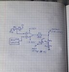
j4CKR.jpg

Originally LM258WYDT (ST) was used as an operational amplifier, it did not heat up, but since it was not from the Rail-to-Rail series, there was a 1.5V drop at the output, which did not allow us to give out a voltage close to 12V. So I decided to switch to Rail-to-Rail, for these purposes I found OP284FSZ-REEL7 (AnalogDevices). After replacing with this amplifier, the value of the output voltage became close to 12V (+-11.85V), but the operational amplifier began to heat up (after 5 minutes its temperature was about 45-60 degrees).
I did not find a short circuit, but noticed that at the output of the voltage divider (R1, R2), instead of 2.5V, the voltage became 4.5V. On the LM258WYDT, this voltage was 2.5V. Perhaps there are elements on this input of the operational amplifier that should lift it?

Unfortunately, at the moment I do not have an oscilloscope and I can not see the output signal.

My suspicions:
  1. The amplifier is not designed for such a load or, conversely, it is not enough for it, and it begins to oscillate.
  2. Is this an accurate amplifier, perhaps additional elements are needed for its operation?
  3. The amplifier is damaged.
 

Hi,

There are Opams and comparators.
Each designed for their application.

If you want (not negative feedbacked) comparator output, then use a comparator.

Opamps are made for
* close to zero differential input voltage (to avoid saturation of internal input stage)
* non sataurated output voltage
* regulation, not switching
....
There are some more detailed discussions about this topic in the forum and the internet.

Klaus

Added: For your application an analog SPDT switch is more suitable. Faster, more precise (calculable) output voltage, no ringing...
 

I did not find a short circuit, but noticed that at the output of the voltage divider (R1, R2), instead of 2.5V, the voltage became 4.5V. On the LM258WYDT, this voltage was 2.5V. Perhaps there are elements on this input of the operational amplifier that should lift it?
Reading the datasheet explains why. Input differential voltage is clamped to +/- 0.6 V. Fortunately the input in your circuit is current limited.

Your schematic doesn't explain why the OP heats up. There are however open points. How did you connect the second unused amplifier? With floating inputs it might oscillate and cause the increased current consumption.

OP284 might show increased supply current in input overload situation. It's not specified in the datasheet. You should be aware that operating an OP as comparator can cause unexpected effects.

KlausST, FvM, Thank you for the answer!


As for limiting the current at the inputs. With a divider, it is probably limited and does not exceed 5 mA. But what happens to a non-inverted input? It is directly connected to the microcontroller, which can produce up to 20 mA.
 

Hi,

Even if the input current is limited... you still mistreat the Opamp in several other ways.
It is not designed for your application.

--> Choose a useful device.

microcontroller, which can produce up to 20 mA.
Many microcontroller "can produce up to 20mA" while keeping on logic level standards...
But the microcontroller will deliver a lot more current if shorted ...but then it will ignore logic output voltage level srandards.

--> The circuit designer is responsible for keeping current within the specified range....not the microcontroller.

Klaus
 

As for limiting the current at the inputs. With a divider, it is probably limited and does not exceed 5 mA. But what happens to a non-inverted input?
The OP is clamping the differential input voltage. Hence it's sufficient to have a current limiting resistor in either inverting or non-inverting input.
 

Status
Not open for further replies.

Part and Inventory Search

Welcome to EDABoard.com

Sponsor

Back
Top