Continue to Site

Welcome to EDAboard.com

Welcome to our site! EDAboard.com is an international Electronics Discussion Forum focused on EDA software, circuits, schematics, books, theory, papers, asic, pld, 8051, DSP, Network, RF, Analog Design, PCB, Service Manuals... and a whole lot more! To participate you need to register. Registration is free. Click here to register now.

Measuring currents in a twin pair of half controlled rectifier

Status
Not open for further replies.

eagle1109

Full Member level 6
Joined
Nov 20, 2014
Messages
390
Helped
4
Reputation
10
Reaction score
7
Trophy points
1,298
Location
Saudi Arabia
Activity points
5,924
Hello,

I'm revising this documents of a company that providing a power electronics experiments board for our electronics labs.

I'm wondering about the measured currents in a half controlled rectifier. As the output current is positive but the currents measured at the lower sides of the thyristor or diode branches are negative.

Here are the oscilloscope signals and the on-book question/answer part.


1. Circuit:
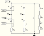
ckt.png


2. Wiring with oscilloscope measuring points:
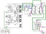
wiring.png


3. Their measured signals:

signals.png


4. Q/A, but I didn't understand the answer quite well .. hope anyone explain it more to me:

qa.png
 

It is a very complicated way to say that the current arrows are drawn in the direction where diode V4 and thyristor V2 don't conduct, which means that the current must have a negative value.
 
I agree with you, both devices would be in reverse bias by that draw !

Except if the author is following the principle that the current flow in the opposite direction, not the conventional idea that tell the direction of current is from +ve to -ve.

But I don't think that is the case because the o/p voltage and current are in positive direction !

So in this way, I agree with you. I don't know what they mean and even I don't have that deep understanding of power electronics.

The training kit and the lab manual is for this company:
**broken link removed**
 

since you are re-writing the documentation, re-draw the schematics and write
the text do they agree with the conventions used in the class.

when you have it re-written, post the new drawings and the
text for review
 
I actually didn't understand what you mean.

We are technical college in Saudi Arabia and the equipment, training kits and documentation is for this company I posted their link which is located in Germany.

This is their catalog which I think they are a professional company, they have good kits and they actually design training labs.

But I'm not re-writing their documentation. I quoting from the manual. And I did some experiments of uncontrolled/controlled rectifiers and it worked ok until now.

I just wanted to know why those currents are negative. But I didn't do that experiment yet. I'm not in the lab right now, I'm in my weekend vacation and revising the manual.

I just wondered the engineering explanation about those currents. But it's not very necessary for me to justify now, I can wait until I reach it, or do a quick test later.

Also, the answer in the red say it's because I'm measuring it from the negative side with respect to ground, so that it's my understanding is the reason that the currents in the oscilloscope graph are negative.
 

They have the shunt/current sense resistors connected to "ground" (the common reference point), so by considering current going to ground as positive, the sign of the voltage on the resistor will correspond the sign of the current.
The wanted to avoid that a negative voltage corresponds to a positive current, but apparently they created some confusion instead ...

It is just a matter of definitions. If you have a +3A load on a battary, you can say that the current is negative when you charge the battery.
You can also say that you charge with +3A and that the current to a load is negative.

Normally, if you know the current direction, you draw the arrow in that direction.
 
Status
Not open for further replies.

Similar threads

Part and Inventory Search

Welcome to EDABoard.com

Sponsor

Back
Top