Continue to Site

Welcome to EDAboard.com

Welcome to our site! EDAboard.com is an international Electronics Discussion Forum focused on EDA software, circuits, schematics, books, theory, papers, asic, pld, 8051, DSP, Network, RF, Analog Design, PCB, Service Manuals... and a whole lot more! To participate you need to register. Registration is free. Click here to register now.

Bias diodes dynamically using Arduino

Status
Not open for further replies.

mondeepsaikia

Newbie level 3
Joined
Jan 30, 2020
Messages
4
Helped
0
Reputation
0
Reaction score
0
Trophy points
1
Activity points
31
I have 10 PIN diodes in series.
I need to switch these PIN diodes on(~11V) for 0.5ms and off for 0.5ms.
How can i do this using arduino or any other microcontroller?
 

The answer depends on what you are using the PIN diodes for. Typically they can be used in high level RF mixers or as RF switches. I can't think of any application that would use 10 of them in series. Please explain.

Brian.
 
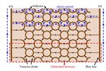
The intended use is to switch the RF response of a surface.
here is an example
[1] M. Saikia, S. Ghosh and K. V. Srivastava, "Switchable reflective metamaterial polarisation rotator," in Electronics Letters, vol. 52, no. 12, pp. 1030-1032, 9 6 2016.
doi: 10.1049/el.2016.0742

The PIN diodes are not switched at GHZ frequencies.
However the surface is operating at GHz frequencies.

In [1] the diodes are switched manually by connecting a DC supply.
I want to switch the diodes using Arduino such that the time for which the PIN diodes are on can be controlled.

~mondeep
 

Hi,

I don't have this document by hand.
What about a hand drawn sketch?

Klaus
 

Capture.JPG

Here Varactor diode is used.
 

Hi,

Do you think this picture is useful for arduino users?

I think your problem rather relates on
* power supply for the diodes
* diode arrangement
* arduino supply and signals (for sure you know "arduino" does not describe the hardware)
* switching device (high side, low side, current)
* maybe current limiting
* maybe HF filters
....
... but I don't know what's exactly your concern...

Klaus
 

I foresee many problems with switching current when there are so many parallel paths through the array.

Question: in post #5 you say Varactor diodes are used but in post #1 you say PIN diodes. Varactors are usually voltage controlled but draw very little current, PIN diodes are the opposite, they are current operated and additionally may need a polarity reversal to fully switch them. They are not interchangeable, which is it you want to use?


Brian.
 

I want to use PIN diodes. The PIN diodes are in series in a similar fashion as the varctor diodes in the figure.
I want to switch them using arduino uno.
Arduino uno can't supply that much voltage and current.
So what kind of additional circuit do I need? (that is compatible with arduino uno)
 

I'm not sure that is possible. With Varactors, the voltage across them decides their capacitance but it is in reverse bias mode, with little current flowing. It is basically just an issue of switching a high enough voltage.

With PIN diodes, ignoring that you may need the polarity reversing, you need to switch current. There are many different paths through your array of diodes that current has to flow through so it would be very difficult to ensure all the diodes had sufficient current to operate. Even if you used a constant current source, shorter paths would hog all the current, leaving longer ones with very little.

In general though, if you want any low voltage MCU to switch a high voltage or high current, look at low side switching. The MCU controls a switch (maybe an NPN transistor) in the ground side of the load with the supply applied to the high side of it. Low side switching means you don't have to elevate the switching signal to a higher voltage.

Brian.
 

Status
Not open for further replies.

Similar threads

Part and Inventory Search

Welcome to EDABoard.com

Sponsor

Back
Top