tiwari.sachin
Full Member level 6
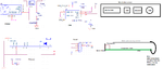
I have 4 connectors
1. Power
2. USB
3. Ethernet
4. USB
All placed in a proper straight line so that when placed in a enclosure, the same are properly flushed.
The body of the connector (Shielding) is done for each of them via a 0.1uF and 1M Resistor to GND.
The outer casing (or the part where these connector sit is of a metal)
Because the cutouts are perfectly in line with the connector size. The metal touches the connectors outer body.
I notice that the board is working fine when i am using it without putting it on the casing but the moment i use the casing, USB doesnot work (I will have to remove it completely and reprogram using a external program) and it works again.
Why could this behavior be happening??
Image of sch and metal slot shown
Attachments
Last edited: