Continue to Site

Welcome to EDAboard.com

Welcome to our site! EDAboard.com is an international Electronics Discussion Forum focused on EDA software, circuits, schematics, books, theory, papers, asic, pld, 8051, DSP, Network, RF, Analog Design, PCB, Service Manuals... and a whole lot more! To participate you need to register. Registration is free. Click here to register now.

LLC converter vs Dual cascaded Buck….1000V to 48V at 500W output…no isolation needed

Status
Not open for further replies.
T

treez

Guest
Hi,
Do you agree that the LLC converter would be more efficient for the above case?
Consider synchronous rectifiers in each case.
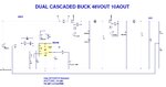
The Buck would be a Dual cascaded Buck so that Duty cycle was not too small….also, the cascaded method means the downstream buck, that carried most current, can have a lower voltage mosfet with lower rds(on).
What I believe I am pinpointing here, is that the LLC is one of the few common isolated converters which suffers no efficiency degradation due to the transformer prescence, since the leakage inductance is just part of the power stage.
Would you agree.
Or what other way would you suggest?
 

Have you considered the "solid state transformer" as
Stage 1? That being a fixed-duty buck with no control
loop at all? These can be made pretty efficient and
no compound-converter-stability issues (such as front
buck seeing a negative load impedance from the second).

I don't think the value of synchronous rectification at
1kV in, 125V out (for example) is worth the complexity
/ cost for a 8:1 stepdown stage. But you can let your
inefficiency-term calcs sort that.
 
  • Like
Reactions: treez

    T

    Points: 2
    Helpful Answer Positive Rating
1000V to 48V, I would do this with 2 x 800V H bridges in series ( we have done up to 4 in series for 3.8kV in, 350Vout 40A )

I would use a series resonant converter ( not LLC per se ) and parallel the rectified outputs ... using 80V schottky rectifiers

much less current in the pri side - easy control - full current limit - even with a short on the o/p

hard to blow up - 85kHz.

- - - Updated - - -

In fact - for 500W 2 x half bridges in series ...

- - - Updated - - -

you can then get the isolation for free ..
 
  • Like
Reactions: treez

    T

    Points: 2
    Helpful Answer Positive Rating
My first thought is that this large a ratio warrants a transformer but I wonder if modern SiC devises make the buck idea more feasible. I'd study a 1-stage implementation and see if its possible. 20:1 doesn't seem completely crazy (everyone is pushing 48V->1V converters these days).

The problem I see with 2 stages is no particularly clear choice for first stage step down voltage. You won't go <100 because why bother doing that without going all the way to 48 but if you're say 200V or above you still need a large high voltage second stage (it's also in the fet no-man's-land. 200-500V fets are barely better than 650V).

If you go 2-stages I think the benefit needs to be no synchronous rectifiers. Now you can evaluate a synchronous 1000V->48V implementation (2 very high voltage switches/gate drives) versus a 2-stage implementation with 1 very HV switch/drive and 1 moderate V switch/drive (but additional diodes and 2 filters).
 

If you were going to do 2 x buck stages - you would have the same gate drive to each stage, this would give 1kV:220V:48V naturally

Using SiC you could synch rect both stages ( only 48V 10.5A out ) - so doable - if you used transformers for the high side gate drive(s) then the top fets for both stages would be easy and gnd ref drive for the lowers ...

kind regards,

- - - Updated - - -

however you lose protection for the o/p if things go horribly wrong - but could use a parallel string of 5W 60V zeners and a fast fuse ( HRC rated ) to protect the o/p too ...

- - - Updated - - -

or a crowbar SCR and fuse ...
 

Thanks yes, the Dual cascaded Buck…all from one controller…..this looks a good shot. No problems with control loops fighting.
I could only do it from 800v in LTspice because theres no 1kv diodes in the simulator. (as attached)
 

Attachments

  • Dual Buck.jpg
    Dual Buck.jpg
    114.3 KB · Views: 129
  • Dual Buck.txt
    6.2 KB · Views: 52
2 x 600V diodes with small snubbers across each, 47pF & 470 ohm should make the sim go ...

- - - Updated - - -

for 1kV in you probably want to keep the sw freq to 50kHz, or even less, and put generous snubbers on everything to limit RFI generation - modest turn on speed of the first fet ...
 
  • Like
Reactions: treez

    T

    Points: 2
    Helpful Answer Positive Rating
Hi
Thanks, the attached (schem and ltspirce sim) is a Dual Buck with the last stage with a sync fet and at 50kHz.
I added a comparator to the COMP pin of the controller …this being done so that the sync fet can be turned off as the load lightens, thus avoiding the sync fet possibly getting turned on for more than a switching period. I set the comparator’s reference to 2V, as I assume the two internal diodes in the LT1243 are 0.7V each, so 2V will be just above that.
The downstream Buck has more voltage across its inductor during the "ON" stroke than in the "OFF" stroke...therefore reverse inductor current sensing is not needed as long as the sync fet is turned off in light load….which it is in this case.
I am actually thinking that the MCP1631 would be preferable to the LT1243, since it will keep switching the FET and not just leave the gate drive low in light load…(which means the sync rect being permanently on due to the sync rect logic circuitry).
Also, the MCP1631 doesn’t have the 2 internal diodes that the LT1243 has…….the voltage of these diodes could be anywhere between 0.5V to 1V…which makes setting the said comparator’s reference more awkward….it would be easier with the MCP1631……..with MCP1631 the comparator ref could be set to about 0.15V and that would be good enough to prevent overly high reversing inductor current.

MCP1631
https://ww1.microchip.com/downloads/en/DeviceDoc/22063b.pdf
 

Attachments

  • Dual Buck plus sync rect.txt
    13.2 KB · Views: 55
  • Dual Buck plus sync rect.pdf
    22.8 KB · Views: 65

... and ... does it work in sim ... ?
 
  • Like
Reactions: treez

    T

    Points: 2
    Helpful Answer Positive Rating
yes the sim works, but there are some ~3ns spikes in the sync fet up to 20A, i presume this could be a simulator thing though...maybe the internal diode in the sync fet is very slow.
I put some 33nH trace resistance in there (plus an RC snubber across the sync fet) , even that didnt really solve it, but took the 33nH inductances out (for now) as they made the sim run really slow.
 
The current spikes are caused by D3 snap-off. The diode is completely useless.
 
  • Like
Reactions: treez

    T

    Points: 2
    Helpful Answer Positive Rating
The following looks good for high input voltage…..its two LLC converters in series, but they share the one transformer and the one resonant inductor.


- - - Updated - - -

Have you considered the "solid state transformer" as
Stage 1? That being a fixed-duty buck with no control
loop at all? These can be made pretty efficient and
no compound-converter-stability issues (such as front
buck seeing a negative load impedance from the second).

I must admit I like this idea for a single stage upstream Buck, dropping the voltage down from 1000v to 400V say. The Buck would just be on a constant duty cycle of 0.4. At startup on no-load, it would run up to the overvoltage threshold, say 450V…and then just sit there until the load was switched ON…sitting there with PWM being in Burst mode from a Burst comparator.
Then as the load pulled current, then it would simply start switching away at 0.5 duty and serve the load, with its inductor being big enough to remain in CCM for Max load down to 50% load…..below that it would end up floating up toward the 450v threshold again…..but drones are likely on pretty much max load to 50% load all the time.
The only other thing that would be needed would be undervoltage lockout…..say set this at 350V….(have a micro to manage this at startup to actually allow it to start up).
Such an open loop buck would not have a control regime to fight with the downstream converter, as Dick Freebird says

- - - Updated - - -

In fact, attached here is an LTspice sim and pdf schem of a "dumb" open loop sync buck, which gives pretty constant 350V output from a 700V input....from zero load to max load, with excellent transient response nil to full load and vice versa.

I wonder why this isnt more common?

- - - Updated - - -

In fact, I have now paralleled two “dumb” open loop sync bucks (constant D = 0.5)…and neither of them hog the current because they are both on open loop.
They give adequate 350V output whether no load or full load and with any load transient. All you have to do is ensure you give them the right Vin.
LTspice sim and pdf schem attached.
They are also interleaved.

Can anybody give a good reason why I should not patent this idea immediately?
 

Attachments

  • open loop sync buck.pdf
    18.3 KB · Views: 69
  • open loop sync buck.txt
    9.7 KB · Views: 53
  • Interleaved sync bucks_open loop.pdf
    26.7 KB · Views: 68
  • Interleaved sync bucks_open loop.txt
    19.5 KB · Views: 53
  • Like
Reactions: asdf44

    asdf44

    Points: 2
    Helpful Answer Positive Rating
Have you tested *several samples* under different load, line and temperature conditions, and validate that there is no condition which would cause current hogging and/or another anomalous behavior?
 

Thanks, no testing as yet...though i believe that we will be clewar of current hogging problems with this parallel open loop Buck.
I stepped the load from full to zero and VV in the sim and it performs well.
Its weakness is that it needs a fixed , known Vin......but in this case we have that.
 

Of course interleaving works in simulation.

In practice I've concluded 'open loop' interleaving is possible if the gate drive duty cycles are reliably matched and care is taken to match layout and some imbalance margin is built into parts (anyone disagree?). Inductors are one of the bigger problems since their R is usually 10% variation at least (copper tempco of 0.4%/C is of some help)


On the other hand I don't know why you're looking at interleaving in this example where power and current levels aren't particularly high and the cost of additional high voltage switches is relatively high? Maybe if you find, say a surface mount fet and you think two of them could do the job with minimal heatsinking I see that making sense. Still decent amounts of cost and size in the HV gate drive alone. And additional control to benefit from interleaved ripple cancellation.


Another concern is no load voltage 'drifting'. If you don't have synchronous fets no load voltage will drift up towards Vin. You'll need a minimum load, clamps or pulse skipping to deal with that.


I do think the open loop first stage is worth some additional consideration since it gives you more freedom choosing the intermediary DC voltage. Your suggested 400V target makes slightly more sense to me than 220V since it's a better utilizes 650V parts in the final stage.


But finally I still think it's worth studying a single stage. Did you rule that out yet?
 
  • Like
Reactions: treez

    T

    Points: 2
    Helpful Answer Positive Rating
So, you want to patent the improved buck converter ? I can't quite see the "inventive step" - legal term - that you have created here ...?

24V to 12V buck converters ( dual fet ) with fixed 50% open loop control have been around for some time - how is your ckt different? [ they work both ways and will step 12V to 24V too ]

In any event you have shared your "breakthrough" on a public forum - so patenting cannot now happen - again patent law.

There are lots of reasons to have the pwm controlled - allows you to use diodes in the lower position - adding reliability ( only 500W )

it affords you current limiting too - something fixed pwm does not

my advice - use the 1kV / 220 / 48V ( 220V is the geometric mean of 1kv & 48V ) with common gate drive and Over Volt stop monitoring on the 220V part ...
 
  • Like
Reactions: treez

    T

    Points: 2
    Helpful Answer Positive Rating
24V to 12V buck converters ( dual fet ) with fixed 50% open loop control have been around for some time - how is your ckt different? [ they work both ways and will step 12V to 24V too ]
Thanks, this is a good point, because I can imagine that if there are say eight or so open-loop synchronous Buck converters supplying the same load in parallel…then do you believe there can be a situation where say 7 of the Bucks are stepping down, but one 'rogue' converter actually steps up? (ie goes in reverse to all the others).

I actually have an LTspice sim of this very thing happening…but in that case it was eight parallel bucks each with transconductance error amplifiers with their error amp outputs all tied together….7 were bucking down, as intended, but one goes in reverse……. Though i did force this error somewhat as I wanted to simulate the case of slightly different tolerances on the error amp reference voltages of each sync buck control chip…….i couldn’t get into the control chips’ innards so I made each ones output divider very slightly different instead.
 

if the layout is symmetric and the fets/diodes the same - the odds are good that they will share to +/- 20% for fixed gate drive...

how is you 1kv -> 48V coming along ..?
 
  • Like
Reactions: treez

    T

    Points: 2
    Helpful Answer Positive Rating
Status
Not open for further replies.

Similar threads

Part and Inventory Search

Welcome to EDABoard.com

Sponsor

Back
Top