Continue to Site

Welcome to EDAboard.com

Welcome to our site! EDAboard.com is an international Electronics Discussion Forum focused on EDA software, circuits, schematics, books, theory, papers, asic, pld, 8051, DSP, Network, RF, Analog Design, PCB, Service Manuals... and a whole lot more! To participate you need to register. Registration is free. Click here to register now.

load sensing circuit/relay

Status
Not open for further replies.

Wdnbob

Newbie level 4
Joined
Jan 19, 2020
Messages
5
Helped
0
Reputation
0
Reaction score
0
Trophy points
1
Activity points
69
I have been digging through various forums and internet articles searching for a current sensing relay circuit that will activate a low voltage relay when the circuit senses a 120v machine drawing 5 or more amps of power.

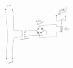
I have hand drawn a schematic and is attached. My desire is to activate a low voltage circuit by simply "closing" the normally open contact of a relay. The article where I got the idea for this schematic calls for a 25amp solid state relay which, in my case, is serious overkill. I only need a very low voltage (12v to 24v) normally open contact closed connection that is most likely be a small milliampere load.

Having explained that, I begun thinking that a opt-coupler type device may be sufficient? Essentially I not sure what to replace the large (size and current) solid state relay with?

In simplest terms the circuit will work like this . . . my (woodworking) circular miter saw starts, the circuit senses my circular saw drawing current and "closes" a normally open relay that will control (start) my dust collector. When finished cutting (release the saw trigger, stopping saw), the circuit sense the lack of current draw and open the contacts to stop the dust collector.

Clearly, I do not have an electronics degree so any help would be greatly appreciated.
 

Attachments

  • load-sensing-circuit_2020-01-19.png
    load-sensing-circuit_2020-01-19.png
    466.6 KB · Views: 222

In principle your design will work but it has some drawbacks, there is an easier way!

The problems are that you drop some of the line voltage in the transformer primary and the voltage reaching the relay is pulsed DC which might make it 'chatter' rather than cleanly operate. You might have to use a MUCH larger transformer than necessary to keep the primary current flowing through to the load. The pulsed DC to the relay is easier to fix by adding a capacitor across the relay coil.

A better solution is to use a small transformer to drop the voltage to the relay coil but wire it across the load so it operates at the same time as the load voltage is present. For most small relays you would only need a transformer rated at < 5VA, with your current sensing method it may have to be rated at hundreds or even thousands of VA.

You can use an optocoupler as an alternative if it is rated for sufficient switching current. Use your original schematic with the optocoupler LED side instead of the relay coil and with a resistor in one (or both) inputs to the bridge rectifier fed across the line voltage. For a small optocoupler I would use 100K in series with the bridge (or 47K in each arm) for 220V line voltage and about half those values for 110V line voltage. The resistors should be rated for more than line voltage and about 1W. Note that by putting the resistors on the line side of the bridge rectifier, it only has to handle low voltage so you can use a small bridge module or four small signal diodes. Add a capacitor (about 10uF) across the bridge output so level out the pulses. Also be aware that the output side of an optocoupler is polarity sensitive.

Brian.
 

Hi,

I assume there are ready to buy solutions. Like "master slave power cords". I use one of such things to switch ON/OFF my periferals if the PC.

I don't want to design your complete circuit...so what's the main problem? The power switch?
You don't like a power relay, then you may use a solid state relay or a triac...

Klaus
 

I have used a small current-transformer with as many (primary) turns wrapped around it as I can fit. The CT secondary goes to a bridge rectifier and then to turn on an opto-coupler's LED (in an SSR) when there is load current. Not enough power to drive a mechanical relay though.
There are power bars and car block-heater cords etc. that have this built in.
 

Not enough power to drive a mechanical relay though.
Depends on the relay size. CT with up to a few W output are feasible. Sensitive relays switching 250V/10A have 0.5W nominal coil power, signal relays considerably less.
 

Thanks everyone for your input.

To those who suggested that there are "ready to buy" solutions out there . . . yes there are but, I am trying to control a low voltage controller. Therefore the typical "control box" sold to do this will not work in my situation.

berwixt,
Attached is a revised schematic with your suggested additions/changes (if I understood them correctly.) Some voltages have also been clarified. Am I stablizing the DC (after the bridge recifier) correctly? (Again, sorry, I have never designed electronic compnoents in this manner before. The extent of my experience is with the use of n/o and n/c switches for controlling high voltage contactor (motor starter type) relays.)SawControl_2020-01-20.png

Again, thanks in advance.
 

When the saw runs, the current passes thru the transformer to generate an output voltage to the resisters and then the signalmoves on to the bridge rectifier. The bridge refecifier converts the voltage from AC to DC and the capacitor "smooths" the DC signal.

Looking for some help on this as I am a novice.

My questions are simple. Are the 47k resistor in the correct locations? Is the 10uF capacitor in the correct location?

Yes, I understand that the opto coupler is polarity sensitive.

Any general help here would be greatly appreciated.
 

Sorry for the delay, I've been busy elsewhere over the past few days.

I don't think you need a transformer and optocoupler, both provide isolation but you only need one. What I was proposing is the circuit you show in post #6 but the two resistors connect directly across the saw motor, after the switch. That way it gives you the output you want and you do not need a big transformer with the voltage losses that come with it.

The 10uF capacitor is in the correct place. Whether you use a relay coil or the optocoupler, the voltage after the bridge rectifier is pulsed DC so a relay will 'buzz' or 'chatter' and the faster reacting optocoupler will produce a fast stream of pulses out. The capacitor is there to level out the pulses so it looks more like a simple 'voltage is there/voltage isn't there' indicator.

Brian.
 

It is quite okay that you are busy. (This is not a "gotta get it done, NOW" project.)

I am not able to put resistors across the motor after the switch. This "sensing" controller box will have a pigtail cord to plug into a standard 120v wall outlet. There will be an single 102v outlet on the controller box to plug the miter saw into. Placing the controller between the wall outlet and the miter saw. If miter saw fails or gets upgraded to newer model, plug in and keep cutting.

Not sure I need the resistors anyway, the original schematic (posted on a woodworking youtube video link) had no capacitor to smooth the dc and no resistors but, a "big" 25amp rated solid state relay which I want to replace with a opto coupler. The original designer was controlling a 120v circuit. He claimed that he had been using his for a couple of years with no problem. I am controlling low voltage and low milliwattage therefore do not need a "monstor" of a solid state relay.

I am going to take this design and do some testing (and more online research) to see if it will not work as is, without the resistors. I suspect it might(?).

When I come up with a final design that works the way I want, I'll redraw the schematic and post here when I feel this has been porperly solved.

Thanks.
 

Situation understood.

What you have to consider when using a series transformer is the voltage drop it adds to the wiring. For example, using a 12V output transformer to drive a 12V relay, it would expect 120V across the primary to produce that 12V. That is the entire line voltage so the saw may not start or at best it would share a portion of the line voltage with the saw motor and both would be unreliable.

Prairiedog and FVM suggested an alternative method using a CT (Current Transformer) this is a special construction of transformer usually used to measure current rather than to power something. It doesn't have a primary winding as such but ONE of the line wires passes through a hole in the transformer and the magnetic field surrounding the wire is picked up and converted to a voltage. You should get enough output to operate an optocoupler but it is extremely doubtful you could operate a relay. There just isn't enough magnetic coupling to transfer sufficient power for a relay coil.

If you want to experiment, and there are too many unknowns to make a calculation, you need something like this:
https://www.ebay.com/itm/DL-CT08CL5...-Micro-Current-Transformer-HH-M-/172206383437
taking the output from the two wires directly to the bridge rectifier then on to the capacitor and optocoupler.

The drawback to using this method is the voltage across the wires is proportional to the current flowing in the wire inside the hole and a load like a saw motor is likely to vary considerably while building up to speed and while under different loads.

Only pass one of the line wires through the hole, if you pass both their fields will cancel each other and you get no output at all !

Brian.
 

Found this and it works

Too bring to a conclusions, I found one of these (see attached photo) that works.6130RU8rJVL._SL1001_.jpg

Yes, a pre-built unit that was suggested by others, thank you.

This one senses AC load thru 30A . . . to improve this, I need to find one with a sensing range thru 10A as I am currently having an issue finding that "sweet spot" setting for the potentiometer.

In my case, buying one is easier than building one (as I am not properly educated in electronics and this type of device.

Thanks everyone.
 

Status
Not open for further replies.

Part and Inventory Search

Welcome to EDABoard.com

Sponsor

Back
Top