idonahum
Newbie level 2
Hi everyone,
As part of the course i took in analog circuit i required to design an amplifier with these values:
Rin= 52kohm
Rout = 53 ohm
A=35 gain in db
F-3dblow = 400hz
F-3dbhigh = 400khz
M1= 40db/dec
M2 = -20 db/dec
Dc supply voltage are : +5 v , -5v
Transitors are ntype BJT
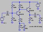
My idea was using a simple CE amplifier with 2 resistors that are parallel to the base port.
I started assuming collector current and tried to find the circuit values that will give me the characeristic i needed.
Every time i found the values i needed and tried to simulate a bias point in PSpice, it didnt work, the collector current was not as i assume and voltages in the circuit were wrong.
I didnt made any progess and i just stand in 1 place and dont understand what im doing wrong.
My questions are then:
1- what am i doing wrong?
2- can u give me specific rules and instruction where to start from and how to get the values i want?
3- do you have any other idea how to design a circuit with these values?
I search the internet and found only specific circuit desgin, it didnt helped me much.
Thanks everyone.
