Continue to Site

Welcome to EDAboard.com

Welcome to our site! EDAboard.com is an international Electronics Discussion Forum focused on EDA software, circuits, schematics, books, theory, papers, asic, pld, 8051, DSP, Network, RF, Analog Design, PCB, Service Manuals... and a whole lot more! To participate you need to register. Registration is free. Click here to register now.

speed control of motor using 89S52

Status
Not open for further replies.

gauravkothari23

Advanced Member level 2
Joined
Mar 21, 2015
Messages
640
Helped
5
Reputation
10
Reaction score
4
Trophy points
1,298
Activity points
6,922
Hi all
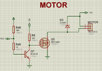
I am trying to control the speed of the DC motor using 89S52 controller using Timer0 Interrupt
Code:
void main()
{
 while(1)
  {
    status_flag=1;
    PWM=0;
    msdelay(5000);
    status_flag=0;
    motor=0;
    msdelay(5000);	 
 }

void pwm_setup()
{
	TMOD &= 0xF0;    // Clear 4bit field for timer0
	TMOD |= 0x01;    // Set timer0 in mode 1 = 16bit mode
	
	TH0 = 0x00;      // First time value
	TL0 = 0x00;      // Set arbitrarily zero
	
	ET0 = 1;         // Enable Timer0 interrupts
	EA  = 1;         // Global interrupt enable
	
	TR0 = 1;         // Start Timer 0
}

void timer0_ISR(void) interrupt 1	
{
	TR0 = 0;    // Stop Timer 0

	if((PWM_flag==1) && (status_flag==1))
	{
		PWM_flag=0;
		motor = 0;
		temp = (255-PWM) * PWM_Freq_Num;
		TH0  = 0xFF - (temp>>8)&0xFF;
		TL0  = 0xFF - temp&0xFF;	
	}
	else if((PWM_flag==0) && (status_flag==1))
	{
		PWM_flag=1;
		motor = 1;
		temp = PWM * PWM_Freq_Num;
		TH0  = 0xFF - (temp>>8)&0xFF;
		TL0  = 0xFF - temp&0xFF;
	}

	TF0 = 0;     // Clear the interrupt flag
	TR0 = 1;     // Start Timer 0
}

my problem is when i am trying to rotate the motor at full speed at PWM=0; it does not. instead when i stop the PWM by writing status_flag=0 and motor=0; the speed increases drastically,
i tried measuring the RPM, when PWM=0, the RPM is approx 2100 RPM and when i stop the PWM and ON the Mosfet the RPM is Approx 2700.

can anybody please let me know where the problem is
 

Hi,

maybe a problem of the hardware?

* Motor driver not able to run with 100% duty cycle?

*****
issues:
* motor=0, motor = 1 is never used, thus it does not do anything else than wrting the value to the variable.
* PWM is 0 all the time.
* PWM_Freq_Num is never used nor declared
* I see no variable declaration at all
* I can´t find out PWM frequency, nor resolution
* and so on....

did you give complete information?

Klaus
 

That's my complete code with circuit diagram.


Code:
#include "REG51.H"
#include "STDIO.h"

sbit motor=P0^7;		  // MOTOR 

bit PWM_flag = 0;

void msdelay(unsigned int value);
	
unsigned char PWM = 0;	  
unsigned int temp = 0;    
bit status_flag;

#define PWM_Freq_Num   1


void main()
{
	while(1)
	{
	     status_flag=1;
	     PWM=0;
 	     msdelay(5000);
	     status_flag=0;
	     motor=0;
	     msdelay(5000);
       }		
	
}    //Main Ends Here		

void msdelay(unsigned int value)
{
 unsigned int i,j;
 for(i=0;i<value;i++)
 for(j=0;j<100;j++);
}
 

void pwm_setup()
{

	TMOD &= 0xF0;    // Clear 4bit field for timer0
	TMOD |= 0x01;    // Set timer0 in mode 1 = 16bit mode
	
	TH0 = 0x00;      // First time value
	TL0 = 0x00;      // Set arbitrarily zero
	
	ET0 = 1;         // Enable Timer0 interrupts
	EA  = 1;         // Global interrupt enable
	
	TR0 = 1;         // Start Timer 0
}

void timer0_ISR(void) interrupt 1	
{
	TR0 = 0;    // Stop Timer 0

	if((PWM_flag==1) && (status_flag==1))
	{
		PWM_flag=0;
		motor = 0;
		temp = (255-PWM) * PWM_Freq_Num;
		TH0  = 0xFF - (temp>>8)&0xFF;
		TL0  = 0xFF - temp&0xFF;	
	}
	else if((PWM_flag==0) && (status_flag==1))
	{
		PWM_flag=1;
		motor = 1;
		temp = PWM * PWM_Freq_Num;
		TH0  = 0xFF - (temp>>8)&0xFF;
		TL0  = 0xFF - temp&0xFF;
	}

	TF0 = 0;     // Clear the interrupt flag
	TR0 = 1;     // Start Timer 0
}

That's the original code which is pasted, but dont know some part of the code gets erased.


Code C - [expand]
1
2
3
4
5
6
7
8
9
10
11
12
13
14
15
16
17
18
19
20
21
22
23
24
25
26
27
28
29
30
31
32
33
34
35
36
37
38
39
40
41
42
43
44
45
46
47
48
49
50
51
52
53
54
55
56
57
58
59
60
61
62
63
64
65
66
67
68
69
70
71
72
73
74
75
76
77
#include "REG51.H"
#include "STDIO.h"
 
sbit motor=P0^7;          // MOTOR 
 
bit PWM_flag = 0;
 
void msdelay(unsigned int value);
    
unsigned char PWM = 0;    
unsigned int temp = 0;    
bit status_flag;
 
#define PWM_Freq_Num   1
 
 
void main()
{
    while(1)
    {
         status_flag=1;
         PWM=0;
         msdelay(5000);
         status_flag=0;
         motor=0;
         msdelay(5000);
       }        
    
}    //Main Ends Here       
 
void msdelay(unsigned int value)
{
 unsigned int i,j;
 for(i=0;i<value;i++)
 for(j=0;j<100;j++);
}
 
 
void pwm_setup()
{
 
    TMOD &= 0xF0;    // Clear 4bit field for timer0
    TMOD |= 0x01;    // Set timer0 in mode 1 = 16bit mode
    
    TH0 = 0x00;      // First time value
    TL0 = 0x00;      // Set arbitrarily zero
    
    ET0 = 1;         // Enable Timer0 interrupts
    EA  = 1;         // Global interrupt enable
    
    TR0 = 1;         // Start Timer 0
}
 
void timer0_ISR(void) interrupt 1   
{
    TR0 = 0;    // Stop Timer 0
 
    if((PWM_flag==1) && (status_flag==1))
    {
        PWM_flag=0;
        motor = 0;
        temp = (255-PWM) * PWM_Freq_Num;
        TH0  = 0xFF - (temp>>8)&0xFF;
        TL0  = 0xFF - temp&0xFF;    
    }
    else if((PWM_flag==0) && (status_flag==1))
    {
        PWM_flag=1;
        motor = 1;
        temp = PWM * PWM_Freq_Num;
        TH0  = 0xFF - (temp>>8)&0xFF;
        TL0  = 0xFF - temp&0xFF;
    }
 
    TF0 = 0;     // Clear the interrupt flag
    TR0 = 1;     // Start Timer 0
}


inside main,
when the status flag is = 1 and PWM is 0
The motor should rotate at 100% duty cycle. which it does not. It rotates at maximum 2100 RPM
but when the status flag = 0 and motor =0;
the motor rotates at full speed approx 2700 RPM
 

Attachments

  • Motor PWM.png
    Motor PWM.png
    76.2 KB · Views: 58
Last edited by a moderator:

Hi,

Some of the issues of post#1 are still unclear. I don't want to ask again...

Before that we take a piece of paper and a pencil to write down the variable values /states..
..I recommend you do this first ... and show us
(I think it's less effort for you, because it's hard to debug foreign, mainly undocumented code. Additionally you should know what values you expect, but we don't)

If I understand correctly you generate ISR driven PWM...
Doesn't the microcontroller include a PWM hardware?

Klaus
 

as per the post 1.
motor=1 and motor =0 is used in interrupt where i am generating PWM when char PWM=0, which means motor to run at full speed.
later while status_flag=0, it means, the i have stopped the PWM and made the mosfet continues ON. where again the motor will run at full speed.
but while using interrupt and making char PWM=0, the motor does not run at full speed.
PWM_Freq_Num is defined a 1 and it is being using inside interrupt.

- - - Updated - - -

its a ISR driven PWM, as the controller does not have inbuilt a PWM hardware

- - - Updated - - -

i Have kept PWM=0; because i need to check the difference between PWM full speed and when the mosfet is fully ON.
 

This is the reading what I received from scope when PWM = 0, but it should be a straight line.
That's what my problem is.

- - - Updated - - -

WHen PWM is = 0,
it should be a straight line, at 100% duty cycle
 

Attachments

  • 20200107_185637.jpg
    20200107_185637.jpg
    521.9 KB · Views: 45
Last edited:

Hi,

temp = PWM * PWM_Freq_Num;
TH0 = 0xFF - (temp>>8)&0xFF;
TL0 = 0xFF - temp&0xFF;
Why are you too lazy to do simple calculations on your own?
Just do it step by step, like the microcontroller should do:

PWM = 0
PWM_Freq_Num = 1
Temp = PWM * PWM_Freq_Num = 0 * 1 = 0 = 0x0000
TH0 = 0xFF - (temp>>8)&0xFF = 0xFF - (0x0000 >> 8) & 0xFF = 0xFF - 0x00 & 0xFF

...what comes first? The "-" or the "&"?

Go on this way.

Klaus
 

& Comes first.
so the statement has to be..??
TH0 = ((temp>>8)&0xFF) - 0xFF;
 

What duties PWM do you want? Are they are some fixed duties or do you want 0% to 100% variable duties?
 

How are you going to vary the PWM duties in your final device? Using a button to increment and another one to decrement?

And between 50 to 100% duties do you want 1% duty steps?
 

How are you going to vary the PWM duties in your final device? Using a button to increment and another one to decrement?

And between 50 to 100% duties do you want 1% duty steps?
I need to reach 100% from 50 in 18 steps.

- - - Updated - - -

How are you going to vary the PWM duties in your final device? Using a button to increment and another one to decrement?

And between 50 to 100% duties do you want 1% duty steps?

I am supposed to use two buttons UP and Down
 

Okay? And what should be the PWM frequency? Can I choose any PWM frequency between 500 Hz and 2kHZ?
 

What is your Crystal frequency? 11.0592MHz or 12MHz?
 

Status
Not open for further replies.

Part and Inventory Search

Welcome to EDABoard.com

Sponsor

Back
Top