Continue to Site

Welcome to EDAboard.com

Welcome to our site! EDAboard.com is an international Electronics Discussion Forum focused on EDA software, circuits, schematics, books, theory, papers, asic, pld, 8051, DSP, Network, RF, Analog Design, PCB, Service Manuals... and a whole lot more! To participate you need to register. Registration is free. Click here to register now.

Newbie question on dynamic mic circuit problems

Status
Not open for further replies.
It's hard to describe as I've tried different things and the noise is different. But the prototype with PDIP works. And this is the only case when everything works.
I'm going to put it on hold for a while as I'm unable to understand what's going on. So I'll continue reading.

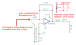
Meanwhile, I'm trying a simpler circuit with electret mic on OPA322. Wish me luck :)
 

Hi,

You designed a PCB ... and it doesn't work.

But you don't show us your PCB, or did I miss it?
You are not the only one acting this way.
And I always wonder what's the reason for this behaviour. Top secret design?

Klaus
 

The OPA322 is an opamp, not a power amp. It cannot drive a speaker like a power amp can but it can drive the input of a power amp like an LM386. The recommended maximum power supply for an OPA322 is 5.5V.
But an LM386 by itself can have a gain of 200 and use a microphone at its input and a speaker at its output.
Good Luck.
 

Hi,

You designed a PCB ... and it doesn't work.

But you don't show us your PCB, or did I miss it?
You are not the only one acting this way.
And I always wonder what's the reason for this behaviour. Top secret design?

Klaus

No, it's copyrighted :))) It's in another thread. Here it is:
trnas PCB.png

It doesn't have a ground plane. But I just wanted to try it (this is my first PCB but Nth try).

- - - Updated - - -

The OPA322 is an opamp, not a power amp. It cannot drive a speaker like a power amp can but it can drive the input of a power amp like an LM386. The recommended maximum power supply for an OPA322 is 5.5V.
But an LM386 by itself can have a gain of 200 and use a microphone at its input and a speaker at its output.
Good Luck.

Yes, I know it's just a preamp. I hope this stage works at least. Then I'll add another stage... That's going to be interesting...
 

You won't win any prizes for that PCB design!

I still don't understand why you are using two transformers, both of them can be removed with no reduction in performance.

Brian.
 

Audio transformers play a role when interfacing balanced lines, also for the noise optimal matching of low impedance dynamic microphones. They are useless for electrete microphones. Operating it with DC bias current like T2 in your circuit is a no-no, also the variable load resistance that forms an unwanted variable high pass.
 

I knew I wasn't a genius but this is worse then I expected...

I made a PCB for the preamp described here on p.19. I used tantalum capacitors 16V, the source is 5V, I double checked all the polarities (including mic) and... it doesn't work. What's worse the chip is heating up (I measured with Fluke).

Well, the pic of the disaster (I know the PCB is ugly and I probably need to stop making them small - well, it's MICROelectronics, so I thought I'd do it):

disaster.jpg

I feel dumb.

One thing I noticed is that they have C1 on p.21 and it's the only place they have it. I don't understand why it's not on other schematics.
Also, I re-used the chip from my first attempt to build this preamp. It could be broken and I don't know how to check this, so I just may to put a new one.

Well, I failed again but I'll try again. With the bigger PCB and the new chip (not used).

Another question on how exactly should I test this. The Vout = ~200mV but this is probably because of failure...
 

Hi,

The PCB size is not the problem.
You could make it half the size ... with a good - working - layout.....or a bad - non working - layout.
The same is true for double size.

I tend to say that a smaller PCB causes less problems than a larger PCB.

But there could be other problems, like:
* bad etching
* damaged traces
* micro cracks in ceramics of Rs and Cs
* ESD damage
* soldering problems
...


Hard to validate...

Klaus
 

Made a new one - very carefully, with the brand new chip. No heating but the Vout is very low (according to Fluke at least).

second attempt.jpg

I wonder if I need to make an amp as a second stage and see what I get then.
 

There are several potential breaks in the tracks on that PCB, if you cleaned it to remove the flux it would be easier to see. However, look at the example PCB in the link and you will notice the input and output sides are at opposite ends of the PCB and almost all of both sides or the PCB are ground areas. Running thin grounds almost randomly around the board will never work. Note also the requirement for a low ESR capacitor across the supply pins.

The IC should not get even remotely warm so I would guess if the PCB is intact, it is oscillating violently due to the layout.

Perhaps if you told us what your ultimate objective is it would help. Adding a pre-amp to a smoking power amp will not fix the problem. I appreciate you are new to this and don't have the benefit of half a century in industry but it does seem like you are not following the golden rule that electronics is 99% inspiration and 1% perspiration. Plan ahead and research the best design and construction strategy before spending money and getting frustrated. I think all of us who have worked in this field will agree that things sometimes don't go to plan but it is much easier to diagnose a problem if the basic rules are followed beforehand.

Brian.
 

The IC should not heat up. Without an input signal, please measure the DC supply and the DC output of the opamp.
I copied the schematic of the TI circuit you made and made a few important notes:
 

Attachments

  • mic preamp.png
    mic preamp.png
    26.3 KB · Views: 161

I'm not that frustrated to give up on electronics :) Not at all. If that one doesn't work, I'll go with transistors, just to make anything work first.
As for my goal, let's say I'm really good at computers but I've never done any electronics. And nowadays the IoT is a really interesting field and there are lots of ideas, so I'm trying to learn the part I don't know.

I'll take measurements next year! :) And I wish you a really great 2020!

Mr. Smoke :)
 

Hi,

I'll go with transistors, just to make anything work first.
How to explain....
I hope you recognized that the PCB layout is bad...
Now it seems that you want to modify parts...not the PCB layout.
The result may be that the new design works (by accident) ... or it may oscillate again ... because of a still bad PCB layout.

--> change what causes the problem, don't change other things.
Don't change the parts, change the PCB layout.
And the design will work.

And the next design will work, too. Independent of parts.

Klaus
 

Hi,
How to explain....
Don't change the parts, change the PCB layout.
And the design will work.
Klaus

Hm... Got it. ok, I'll do it!

I haven't got into PCB design in my reading anywhere yet. I'm on op amps territory still...
 

Hi,

Opamps need a PCB layout...

Many datasheets contain PCB design informations, some include example PCB layouts, some refer to dedicated application notes and/or design notes.

My recommendation:
* use double sided PCBs
* there are a lot of documents and even videos on "how to" homebrew double sided PCBc.
* solder side is GND, nothing else
* components and traces are on opposite side

There are cheap PCB board houses for good quality (better than homebrew) PCBs.

Klaus
 

... and don't be put off by Klaus recommending double sided boards. It doesn't necessarily mean placing tracks on both sides if you are making boards at home. When you have to make double sided boards it can be a nightmare to accurately align the two sides unless you have CAD available. Just think of the 'second' side as being a very good ground which is available anywhere on the board by drilling a hole and passing a wire (maybe a component leg) through wherever a ground connection is needed.

It is difficult to visualize but copper tracks, especially thin ones have undesired properties like inductance and resistance. They are not particularly good conductors and that means a voltage is dropped along their length as a current passes through. That voltage may be very small, in your case probably microvolts, but in an amplifier circuit if it reaches the input it gets re-amplified over and over again until the circuit becomes completely unstable. As you work with RF, the inductance of the tracks starts to play a bigger role in their performance but even at audio it can be significant.

Other general rules:
1. try to keep the input and output ends of an amplifier as distant as possible from each other to minimize the chance of output reaching back to the input stage.
2. very important - make sure all supply pins are decoupled with good quality capacitors and as close to the supply pins as possible.

Brian.
 

ok, the beginning of the year is going to be interesting! I'll try to make a double sided board then following the suggestions.

I could order a PCB but the turnaround time is about a week. Not acceptable for me as I can make it in an hour myself. I'd do that when everything thoroughly tested.

Let me see how they make double sided PCB's...
 

Make it the way you already have but start with double sided board. You do not need to etch the ground side, just leave it as plain copper.
It is actually pretty easy to make 'pro' quality boards at home if you have a printer and a CAD package (I use Kicad which is free and multi-platform). Draw the schematic in the program first, then save it as a netlist (a list of components and how they connect to each other) and finally import the netlist into the PCB designer. You can move the parts around until you are happy with the layout, either auto-route the tracks or draw your own (Kicad will help you by showing which points need linking) and then print it. There are several ways to transfer the printed tracks on to copper but my preferred method is to use photo-sensitized board (or coat your own with photosensitive paint) then expose it to a UV light source for a few minutes. You get perfect results every time, even with very fine tracks and you can re-use the artwork over and over again.

Brian.
 

Yes, that's what I've been doing since the beginning - I use Circuit Maker and make photo templates with inkjet printer. Then transfer it to PCB exposing the template. This way it's possible to make 0.1 mm tracks. So yes, I can definitely make it.

Actually, after all the attempts I can do this very quickly now :)
 

You used tantalum capacitors which are polarized instead of using film capacitors which are not polarized. Did you measure voltages like I asked to see if the capacitors had the correct polarity? The input capacitor has a biased electret mic at one end and a biased opamp input at the other end. Which end is more positive? It is very important for the opamp bias filter capacitor to have the correct polarity.

Do you know the resistor color code and are the colors clear? Maybe one of the opamp bias resistors has the wrong value which is why I asked you to measure the supply and output voltage of the opamp. What are the voltages?

Did you try adding the supply bypass capacitors that I showed? Since most opamps will oscillate and not amplify without them then the article you copied assumed that you used them.
 

Status
Not open for further replies.

Similar threads

Part and Inventory Search

Welcome to EDABoard.com

Sponsor

Back
Top