Continue to Site

Welcome to EDAboard.com

Welcome to our site! EDAboard.com is an international Electronics Discussion Forum focused on EDA software, circuits, schematics, books, theory, papers, asic, pld, 8051, DSP, Network, RF, Analog Design, PCB, Service Manuals... and a whole lot more! To participate you need to register. Registration is free. Click here to register now.

Basic 12v Battery VOLTAGE METER, more resolution needed

Status
Not open for further replies.

kingtal0n

Junior Member level 3
Joined
Jun 14, 2016
Messages
31
Helped
0
Reputation
0
Reaction score
0
Trophy points
6
Location
Florida
Activity points
552
Hello,
I am trying to use ( LM3914 ) like this:
https://circuitdigest.com/electronic-circuits/lm3914-voltmeter-circuit

As a voltage meter, lighting LED one at a time based on voltage.

My question is, the way the circuit is normally setup is to light each LED per 1.5v 'steps' give or take

What I want it to do instead, is only show me from say 10v to 14v range, instead of 0-15v range.
In other words I'd like more resolution between 10 and 15 volts and to basically ignore the 0-10v range (because the battery never goes that low)

I am trying to use it to show whether the in-car alternator is working or not. Alternator puts out 14v~ when charging and only battery voltage (10-12v depending how dead it is) when the alternator fails.


thanks for looking!

- - - Updated - - -

I found this and I think it answers my question, will update when I produce a project
**broken link removed**
 

There are 7-Segment Voltmeter kits with 3-Digits at aliexpress.The cost is lower than what you do by yourself
 

There are 7-Segment Voltmeter kits with 3-Digits at aliexpress.The cost is lower than what you do by yourself

Can you please elaborate, I am new to all of this....

I see tons of them and trying to make sense of it

You mean this by any chance?
https://www.aliexpress.com/item/400...chweb0_0,searchweb201602_3,searchweb201603_53


Sorry it takes me a minute

- - - Updated - - -

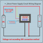
So for something like this
https://www.aliexpress.com/item/328...7.0&pvid=c36700b7-b9ca-4cf8-943a-421ff4be4687

voltandampmeter.png

I notice some kind of adjustment on the back, I think its for resolution? using at lower voltage?

Other question is, I notice the load ground going through the amp-meter. Does that mean it MUST act as a sink for the 10A of current? OR are they simply not showing the actual GROUND for the load going somewhere else...

thanks for the heads up btw

Right now I'm thinking I will use one for voltage and also measure the amperage of my fuel injectors or something like that. Just for the heck of it. The device is $1
But I'm curious if there is some other, larger use for the amp-meter that I am not thinking of. I can't use it for the alternator charging current (100amps) clearly. Or the fuel pump (15amps+). Or starter (300amp?)
 

Your k7tty.com link appears suitable to provide expanded scale. I built similar voltmeters. It has instant response to voltage. I can see where it drops to in the first 1/10 of a second when cranking the engine. Thus it tells me something about battery health.

I adjusted mine to yield a range of 7 to 16V in steps of 1V. (Two or more 3914 IC's can be cascaded for closer resolution.)

I know of no other type of meters that gives such instant response, neither my old-fashioned D'Arsonval needle type nor digital type.
 

I notice some kind of adjustment on the back, I think its for resolution? using at lower voltage?...

No, it won't work; because the driver for the display takes the power from the same battery and the ground is common.

You need to have an offset (say 10V) and then apply the voltage to the input. The ground is common...

Let us say you put a 10V zener and a 10K resistor to the battery; The voltage across the resistor will now be reduced by 10V.
 

Your k7tty.com link appears suitable to provide expanded scale. I built similar voltmeters. It has instant response to voltage. I can see where it drops to in the first 1/10 of a second when cranking the engine. Thus it tells me something about battery health.

I adjusted mine to yield a range of 7 to 16V in steps of 1V. (Two or more 3914 IC's can be cascaded for closer resolution.)

I know of no other type of meters that gives such instant response, neither my old-fashioned D'Arsonval needle type nor digital type.


This is a great thing to hear. Thank you. I Want to make one of these. I have several chips so I may just string couple together to get a ~0.5v resolution give or take. that'd be nice.

questions abound
I wonder how some of the circuit components work. For example the H1 (inductor) on the input, "choke". To protect from high transient spikes.

I don't have this item, I've never used an inductor before, how do I tell using electrical knowledge exactly how important it is or how it works in this instance? Is there a calculation I can do on paper for this sort of thing- of course there is. But I am not handy with that. What are your thoughts if you don't mind me asking on these type of improvements?

- - - Updated - - -

No, it won't work; because the driver for the display takes the power from the same battery and the ground is common.

You need to have an offset (say 10V) and then apply the voltage to the input. The ground is common...

Let us say you put a 10V zener and a 10K resistor to the battery; The voltage across the resistor will now be reduced by 10V.

I'm not sure you understood what I meant. On the back of these devices is typically a little adjustment knob that you turn with a screwdriver.

I just wanted to know what it is for. the instructions I found online do not mention it, at least thus far
 

Its a long time since I used an LM3914 but I think it's possible to lift the bottom of the divider chain above ground to set the minimum reading. The LEDs then display linear steps from bottom to top of the divider chain. The internal reference can be adjusted up to 12V but I think, and it isn't clear from the data sheet, the reference can be disconnected and a higher voltage applied to the top of the chain. So fixing 10V at the bottom and 15V at the top might be all you have to do. I think all the inputs are OK to to about 25V.

Brian.
 

Its a long time since I used an LM3914 but I think it's possible to lift the bottom of the divider chain above ground to set the minimum reading.

There is one example in the application notes that can be used to set the lower point (the voltage needed to light up the first LED) and also the steps for the next LED.
 

Hey everyone, thanks for the support, I finally got a chance to throw a project together and got it working! (All in 1 day lol)

So it appears to work great on the bench. Here are my issues/questions I hope you can help :D

1. The 83Ohm resistor seems to get warm. Very warm. If I had to guess it seems to level out around 150*F or so.
Is that an issue? too hot? The device works, doesn't burst into flame. But what the heck?

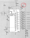
Heres a picture of the hot resistor and full schematic I used. The only thing I did different was the 'C1' .1uf cap, I used a weird looking .15uf cap instead (it was all I could find today on short notice) Actually Im not even sure it IS a capacitor lol. Its like some kind of white brick. It says ".15J100" on it.
1.png


2. How in the @!*&# am I going to get this thing transplanted off my bread board and onto some kind of actual hard-soldered circuit?

Is there any easier way than just using a blank board and trying to forcefully solder everything and... um... I've never done that before


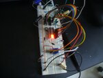
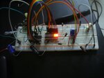
picture! Its so pretty
P1330274.jpg
 

Attachments

  • P1330273.jpg
    P1330273.jpg
    400.1 KB · Views: 64
Last edited:

Hi,

1. The 83Ohm resistor seems to get warm. Very warm.
R7 is already marked "2W". You must not ignore this information.
(EDIT: originally I wrongly wrote "C7")

Did you install a suitable resistor?

Klaus
 
Last edited:

Hi,


C7 is already marked "2W". You must not ignore this information.

Did you install a suitable resistor?

Klaus

I think you meant R7. The resistor I used is 5Watts I think, it says on the side. So I guess its suitable. It doesn't get hot enough to boil water but it does get so hot I can't keep my hand wrapped around it.
 

Is there any easier way than just using a blank board and trying to forcefully solder everything and... um... I've never done that before

Congratulations on getting your project to work. Since you're in bargraph mode there can be 1/2 or 1 watt going through the safety resistor. That is so warm you can't hold it between your fingers.

I usually selected dot mode for my 3914 voltmeters.

Most of my projects are on perfboard.
Dual-inline-pin IC's.
Through-hole components.
Most connections with uninsulated hookup wire.
Everything easy to work with and to solder.

I've also used the boards with a grid of copper pads around the holes. Some have a connected row for supply rails.

The advice for hobbyists is to use IC sockets. Solder to their pins. Don't install the IC until everything is soldered.

Arrange components so you can connect them by short lengths of wire. Although it makes sense to reduce the space occupied by your circuit, consider that you may want to make it easy to unsolder and replace components, in case you revise and improve it.
 

Hi,

I think you meant R7.
Thanks.
Yes, I meant R7.
Sorry for that. I correct it in the original post to avoid further confusion.

And as Brad says:
5W rated resistors may go up to more than 150°C with full power, so even 1W will cause the temperature to be high enough you don't want to touch it.

Klaus
 

Hi,

Good work! To add to Brad's suggestions: Have a detailed drawing/schematic of the actual components on the pcb that is exactly the layout you have chosen and as you solder components and wires, colour them in on the drawing to know what you've done and what needs to be done still. Use different coloured wires to know power, ground and assorted signals - makes troubleshooting easier if needed later on. On perfboard, painters tape can help to keep components in place if bending wires doesn't. Remember, you solder a reversed image of the circuit. A photo of the unsoldered board can help, too to remember where each component goes.
 

Hi,

And sometimes it's useful to take a photo from the component's side, then mirror it on the PC and print it out.
This way you see the components from "bottom view"..

Klaus
 

As I see it, the only purpose for having R7 at all is to drop the LED voltage to about 2.5V across the four diodes. I'm not sure why that is necessary as the LM3914 already contains current regulated outputs. Simply removing the diodes will probably fix the issue. If they then vary in brightness according to how many are lit up, either program them to lower current or add a resistor in series with each LED.

There is an example of a similar application in the data sheet.

Brian.
 

Hi,

I'm not sure why that is necessary as the LM3914 already contains current regulated outputs.
And this I think exactly is the point "why".

If the voltage drop (and power dissipation) is not done externally, then all the (same) power dissipation needs to be done in the LM3914. It will probably overheat.

Klaus
 

Agreed Klaus, but using the diodes as a shunt voltage regulator like that means they have to pass more than the combined current of all the LEDs in 'on' state to ensure the voltage stays steady, that is very inefficient. I suppose it really depends on how much current the LM3914 is programmed to pass through the LEDs but a smaller resistor in series with each LED would certainly avoid the single hot component and only illuminated LEDs would create any heat at all.

Brian.


IF someone has the time, I would like to know more about the use of these diodes as a 'shunt' voltage regulator?

For example, Does it matter if I use 3 diodes or 4 diodes or 2? I don't quite understand what is happening there on the end of the ground string. I know the basic purpose of a diode and I believe there is a voltage drop after each (I get 12.2v going into the circuit and 11.5 or 11.8v coming off the first diode going into the circuit to begin with)

they have to pass more than the combined current of all the LEDs in 'on' state to ensure the voltage stays steady, that is very inefficient.
This makes some sense to me. I think I want to try what you are saying, remove the big fat resistor and use smaller individual resistors for each LED.
So I think you are saying I can remove the 4x diodes from the end and remove the 83W resistor all by simply using a bunch of individual resistors for each LED? What like 300Ohm each?
I am terribly new to this... sorry...

I'll get some random soldering board and I am very lucky to have access to my college's engineering supplies, irons and stuff, so pretty soon I should be able to solder something up
 

That is exactly right. I will try to explain my reasoning about the shunt regulator method:

A diode blocks the flow of current in its 'reverse bias' condition (when the anode is more negative then the cathode) and allows the flow when it is the other way around. In conductive direction, it has a voltage threshold at which it starts conducting, below the threshold the current will be very low, as it reaches it the current suddenly increases. The threshold for most silicon diodes like the 1N4007 is around 0.65V, it varies slightly from one type to another but not by much. We call it "Vf" or the forward voltage. If you look at data sheets for diodes you will usually find a V/I graph that shows the threshold and the Vf staying fairly steady as the current increases beyond it. Vf does increase with current but a large change in current will only cause a small change in Vf. This is the property that allows it to be used as a stable shunt regulator. Regardless of the current flowing through a diode, the voltage across it will stay relatively constant.

Passing current through R7 to the four diodes in series produces a stable drop of about 0.65V per diode and therefore (4 * 0.65) = 2.6 Volts in total. From ground, the D5 will have about 0.65V across it, at the top D4 there will be about 1.3V, top of D3 will be at about 1.95V and the top of D2 will have the full 2.6V on it. The circuit uses that 2.6V as the supply for all the LEDs, the other end of the LED is effectively grounded by a switching circuit inside the LM3914 to make it light up.

We call it a 'shunt' regulator (as opposed to a series regulator) because it dumps excess current to ground rather than restricting the amount made available to be used.

Here's the problem:
Lets suppose the current through each LED is 10mA.
With only one LED lit up, 10mA flows. With 10 LEDs lit up 100mA flows. So R7 has to be capable of dropping the voltage down to 2.6V at the maximum load of 100mA to cater for all 10 being lit at once. As the voltage it drops is proportional to the current flowing through it (Ohms Law, V=I x R) when less than 10 LEDs are passing current, the voltage it drops will also be less and the remaining LEDs will have excessive current flowing through them. The shunt is there to prevent that happening, the idea is that R7 passes a fairly constant current so the voltage supply to the LEDs stays steady, any current NOT flowing into the LEDs goes through the four diodes instead. As more LEDS light up and draw current through themselves, less goes through the 1N4007s.
Unfortunately, that means R7 has to pass maximum current regardless of how many LEDs are actually lit up.

If you forget R7 and the four 1N4007 diodes and instead add a resistor in series with each LED, you limit the current the LED can pass when it is lit up but pass no current at all when it isn't lit up, far more efficient!

Brian.
 

Status
Not open for further replies.

Similar threads

Part and Inventory Search

Welcome to EDABoard.com

Sponsor

Back
Top