vaibhavwaman
Newbie level 4
We are using load switch and current limiting resistor to charge supercap from 5V, As we have 3.3V available at source we convert it to 5V using boost converter to charge supercap till 5V to get more backup time.

We are using FPF2125 switch to protect reverse current flowing from supercap to power supply when power is off.
As per calculation I am getting practically 70mA current limit, which is correct. but I have question regarding turn on threshold,

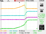
In image :
Channel 1 :Vds of PMOS that is in and out pin of FPF2125
Channel 2 :Output current
Channel 3 :Voltage across resistor
Channel 4 :Input Voltage
1.I have connected On pin to input of FPF2125 what will be turn on threshold, because as per my understanding it should be 1.8V but I see in waveform at 2.4V. Is it due to turn on delay ?
2. How shall I calculate power loss including derating in active region of PMOS inside FPF2125. As per my understanding active region is mention between two curves ?
FPF2125 datsheet :
https://www.mouser.com/datasheet/2/149/FPF2125-191153.pdf
Thank you.

We are using FPF2125 switch to protect reverse current flowing from supercap to power supply when power is off.
As per calculation I am getting practically 70mA current limit, which is correct. but I have question regarding turn on threshold,

In image :
Channel 1 :Vds of PMOS that is in and out pin of FPF2125
Channel 2 :Output current
Channel 3 :Voltage across resistor
Channel 4 :Input Voltage
1.I have connected On pin to input of FPF2125 what will be turn on threshold, because as per my understanding it should be 1.8V but I see in waveform at 2.4V. Is it due to turn on delay ?
2. How shall I calculate power loss including derating in active region of PMOS inside FPF2125. As per my understanding active region is mention between two curves ?
FPF2125 datsheet :
https://www.mouser.com/datasheet/2/149/FPF2125-191153.pdf
Thank you.