Continue to Site

Welcome to EDAboard.com

Welcome to our site! EDAboard.com is an international Electronics Discussion Forum focused on EDA software, circuits, schematics, books, theory, papers, asic, pld, 8051, DSP, Network, RF, Analog Design, PCB, Service Manuals... and a whole lot more! To participate you need to register. Registration is free. Click here to register now.

In accuracy in AC Voltage measurement

Status
Not open for further replies.

AakashDey

Newbie level 4
Joined
Apr 29, 2019
Messages
6
Helped
0
Reputation
0
Reaction score
0
Trophy points
1
Activity points
48
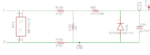
I want to measure the AC voltage through controller (ESP32). So, I have designed a schematic which is attached. As per as my calculation, for 230VAC voltage. the voltage after the divider should be 2.76V. But, practically I am getting 1.9V. Similarly, with 110VAC I am getting 1.2V in practical.

Why I am getting such inaccurate voltage after the divider?
 

Attachments

  • sch.png
    sch.png
    13.9 KB · Views: 301

Main problem is Z-diode leakage current. Diode characteristic isn't that steep as you apparently expect. Additionally may be ESP32 input current.
 

Thanks for the suggestion. I have measured the voltage after removing the Z-diode. Now, I am getting the accurate voltage after the divider.

Actually, I have used the zener diode to avoid any over voltage to the Controller. So, as the leakage current of the Z-diode is creating problem, so what can I use instead of Zener for over voltage protection in this case?
 

ESP32 maximum ratings suggests that IO pins have clamping diodes, but there's no current rating. For additional safety, you may place external clamping diodes (low leakage schottky or general purpose silicon diodes) and a series resistor (e.g. 1k) between clamped voltage and analog input. Or use an external buffer.

As a side remark, your measurement circuit can only work if either the AC voltage is isolated against circuit ground (transformer) or the circuit ground is floating.
 

Thanks for the reply. But what I need is over voltage protection. As you suggested, How a schottky diode and a resistor in series between clamp voltage and analog voltage without using the zener diode? I am not able to understand the schematic what you suggested.
 

Hi,

there are many discussions, documents and even videos about overvoltage protection with clamping diodes. I assume millions.
Just do a search.
Even here in the forum are many threads.

Klaus
 

The semiconductor companies sell double diodes which are specifically designed to protect microcontroller inputs from an overdrive.
These have low leakage and low Vf.

Having said that, if your application is going to be used mostly at room temperature, even a low cost dual schottky like the BAT54S can be employed.
 

Hi,

even a low cost dual schottky like the BAT54S can be employed
ST BAT54S datasheet says:
* typ: 0.05uA @ 5V and 25°C.
* typ: 0.45uA @ 5V and 50°C.

I assume this error may be a factor of 1000 better than a 5.1V zener diode (in breakdown direction).

Klaus
 

I have design my circuit with Diode clamp. I have used BAT54S to clamp the voltage at 3.6V. But, the main concern is that we are not going to use the circuit in room temperature. So, is there any possibility of leakage current in the new circuit ? Also, I have used 1K resistor as shown in figure. Is it OK? Please advice.

SCH_New.jpg
 

Hi,

* I gave the leakage current at 50°C
* You worry that you use it not only at room temperature. This is somehow useless information.
What temperature else? -50°C? +100°C? +300°C?
* ESP32 analog input refers to GND, but your circuit does not show GND
* I recommend to use a noise filtering capacitor

Klaus
 

Thanks.
- We are going to use it from +40°C to +70°C. According to this conditions, Is my circuit will able to measure the AC voltage accurately (1-2%).
-Check the ground (GND). I have connected the capacitor (0.22uF). I think, it is OK?
- Is 1K resistor in series with the Ferrite bead (270K) is fine as shown in figure?

SCH_2.png
 

Hi,

Is my circuit will able to measure the AC voltage accurately (1-2%).
I assume what you want to ask about is precision, not accuracy.

My answer is: No.
Not because the ferrite bead, the 1k, or the BAT54. No, mainly because of the measurement method.

AC measurement, different techniques and their precision problems have been discussed here in the forum many times.
Just do a forum search.

Your analog circuit is close to the "rectified average" method. The expected ripple is less than 1LSB (but it's measurement response time is very slow). I assume you want to show the result as "RMS" value. But you may use "rectified average method" only when you have known and stable waveform. As soon as there is some distortion/modification on the waveform you will see a difference (error) between your value and true RMS value.
For variable waveform: no other measurement method can replace true RMS method.

Diode error:
Your source impedance is mainly determined by the 10k resistor...with the 1k in series it makes about 11k.

You don't tell about ADC input range, thus I just take 3.3V as example.
2% of 3.3V is 66mV allowed error. (Percent calculation)
66mV at 11k means 6uA. (Ohm's law)
Thus your allowed diode leakage current error is 6uA. (Both dides in combination, where one diode compensates a part of the other diode current. Worst case points are at GND and VCC)

Klaus
 

Thanks for the valuable suggestions.

What I exactly want know how accurately I can measure the AC voltage with the new Schematic (Clamp Diode method)? Because, previously for 230VAC, instead of 2.76V I was getting 1.9V at the ADC pin.

I will definitely search the different methods of AC voltage measurement.
 

Hi,

Again: Precision or accuracy?

Again: there is no general answer, because we don´t know your exact waveform, whether there is (variable) distortion, noise and so on...additinally again: we don´t know your ADC input range.

****
What you say "AC voltage" .. I assume you mean "AC RMS voltage". If so, then the best way is to measure/calculate RMS voltage. Everything else means you accept errors.

Klaus
 

Status
Not open for further replies.

Part and Inventory Search

Welcome to EDABoard.com

Sponsor

Back
Top