neazoi
Advanced Member level 6
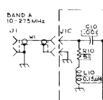
Hi, attached is the input circuit of a spectrum analyzer.
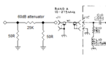
I want to build a 60dB 1W 50R I/O attenuator which will be connected to the input of the spectrum analyzer.
I am confused a bit about the next things:
1. What is the difference between the two attenuation pads, T-pads and Pi-pads? Do Pi-pads shunt the signal to ground and T-pads reflect it?
2. Should I calculate the pad for 50R I/O impedance and just connect it to the input of the analyzer? I worry because for example on a Pi-pad, the output shunt resistor will be effectively connected in parallel to the 51R resistor which is inside the analyzer input, so won't this be 25R instead?