abomin3v3l
Junior Member level 1
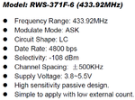
I have a prototype board which has two RF modules on it, a 2.4GHz Wifi module (ESP-01) and a low cost 433.92MHz RF receiver module (Wenshing RWS-371F-6). My 433MHz transmitter (a remote control) sends data encoded in manchester to be decoded by the receiver, this part is working well. The data rate is 2000 bits per second and I am using 433.92MHz SAW ressonator on the remote control PCB prototype. I have a frequency meter, and its transmission frequency is exactly at 433.9MHz constantly. When the ESP-01 module is not connected to the board, I can control the relay of the board from 50 meters distance with short presses on the buttons of the remote control, and it almost always work at this distance (to control the relay). When the ESP-01 module is connected to the board, the 433MHz RF performance is very poor. For example, from only 5 meters distance I have to do a long press on the button in order to control the relay, and sometimes it does not work. And with the ESP module connected to the board, It does never work doing short presses on the button like works when the ESP-01 module is not connected on the board...
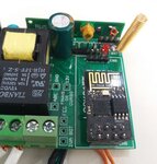
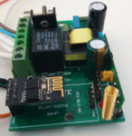
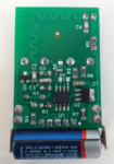
As can be seen on the photos, I have tested 433MHz module antenna with helicoidal and straight wire (17,3cm and 13cm), and with 13cm long wire the result is even worst.
This board have 12V (100KHz - LNK626DG) power supply that is generated from the mains, then the 12V is reduced to 5V (7805) and 3.3V (LM1117IMP-3.3), two linear voltage regulators. The board has a ground plane also, shared by all them.
The only thing connected to the 5V output is the 433MHz RF receiver. At the input of 5V regulator I have a 100nF ceramic, and at output 10uF ceramic 0805 16V, and at the two 5V supply pins of the 433MHz module I have a 100nF ceramic. I have checked the 5V rail with a scope, and there is very low noise there, almost a straight line. When the ESP module is connected or when not connected, I have observed almost the same signal on 5V line. The ESP-01 is being supplied by a regulated 3.3V (this power supply will be changed by a buck converter of 1.5MHz on the next prototype). At the output of this regulator I have one 22uF ceramic, and very close the the 3.3V pin of the ESP module I have 2x 22uF 0805 10V ceramic capacitors.
In that board it is also possible to connect a bluetooth module like the HC-05 (bluetooth is also 2.4GHz) in place of ESP-01, and when the BT module is connected to the board and working, it does not cause interference on the 433MHz RF like the ESP module do, maybe due to the low-power RF of bluetooth.
I have noticed that the 3.3V output is at one edge of the PCB and the ESP connector is at the other edge of the PCB... and there is a 3.3V trace crossing the PCB from one side to another.
Do somebody know if is it possible in my board, to have a good performance on 433MHz RF and use the ESP module at the same time? Because in my board the ESP module seems to be causing interference on the 433MHz module's receiving capability.
Why is this interference occuring? And what could be done to solve?
Is it layout issue?
Datasheet of the 433MHz receiver module: www.web66.com.tw/_file/C3/31776/Dfile/1402897191832file.pdf?t=2019091807
Regards


