pooh_bear
Newbie level 5
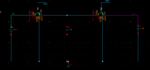
When I simulate a switched capacitor circuit for with PSS, PAC and PNOISE, the PNOISE does not come out right.
I was expecting the output noise to be 4KT(1/(f*C)) just like it would be a for a continuous time RC filter.
Rswitch = 0.01 + 10 Ohm (noise generation is enabled for each resistor)
Fsw = 1MHz
Cfly = 1pF
Cout = 8pF
If I have a continuous time RC I get the expected noise :
R = 1MHz
Cout = 8pF
Vn^2/Hz = 16f V^2/Hz
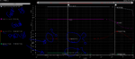
I am getting pnoise values that don't make sense. It does not come out to be the 16f V^2/Hz value and there is a lower frequency conent that creeps up.
Any help is appreciated. Thanks~
I was expecting the output noise to be 4KT(1/(f*C)) just like it would be a for a continuous time RC filter.
Rswitch = 0.01 + 10 Ohm (noise generation is enabled for each resistor)
Fsw = 1MHz
Cfly = 1pF
Cout = 8pF
If I have a continuous time RC I get the expected noise :
R = 1MHz
Cout = 8pF
Vn^2/Hz = 16f V^2/Hz
I am getting pnoise values that don't make sense. It does not come out to be the 16f V^2/Hz value and there is a lower frequency conent that creeps up.
Any help is appreciated. Thanks~