schmitt trigger
Advanced Member level 5
In this and other forums, the question arises whether the same low power transformer used in the power supply, can be used to obtain an isolated sample for a zero crossing detector.
I remember many years ago that there was a small error, but could not remember the magnitude.
Thus on a lazy Sunday with nothing better to do, I rigged a small setup and measured it. I decided to share it, for future reference.
See attached photo.
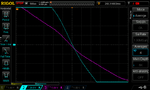
The light blue trace is the actual 120V, 60 Hz line viewed with a 100X diff probe. This voltage is applied to the transformer's primary.
The magenta trace is the voltage coming out from the transformer's secondary.
It can be seen that the secondary voltage leads about 100 microseconds, which on a 60Hz powerline means around a 2.2 degree error.
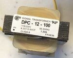
For whatever it is worth, the photo shows the transformer I used. It is a very small transformer and therefore the L/R ratio is small. I suspect that larger transformers would have even less phase shift.
I remember many years ago that there was a small error, but could not remember the magnitude.
Thus on a lazy Sunday with nothing better to do, I rigged a small setup and measured it. I decided to share it, for future reference.
See attached photo.
The light blue trace is the actual 120V, 60 Hz line viewed with a 100X diff probe. This voltage is applied to the transformer's primary.
The magenta trace is the voltage coming out from the transformer's secondary.
It can be seen that the secondary voltage leads about 100 microseconds, which on a 60Hz powerline means around a 2.2 degree error.
For whatever it is worth, the photo shows the transformer I used. It is a very small transformer and therefore the L/R ratio is small. I suspect that larger transformers would have even less phase shift.