Georgy.Moshkin
Full Member level 5
While combining some fabricated blocks I observed following behavior:
Antenna module: Wideband antenna with 3GHz bandwidth, input impedance is 100 Ohm.
Receiver module 1: FET based mixer receiver with some complex impedance.
Receiver module 2: FET based mixer receiver with some complex impedance + matching structure to 100 Ohm.
All components work perfectly when used matching receiver. But with "raw" reciever there is something that I do not understand.
While performing frequency sweep from 25 to 27GHz, received signal have significant (6 to 12dB) dips each 200-300 MHz, for example at 25, 25.3, 25.6, 25.9, 26.2GHz and so on. I expect to see such dips spaced much more sparsely. Overall path length between parts including free space is less than 10cm.
Simulation shows, that for mismatched case impedance could not "swirl" so many times through smith chart. What I am missing here?
Unfortunately I do not have VNA to see what is actually is happening during frequency sweep.
- - - Updated - - -
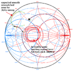
Here is some image for explanation purposes:

At first I thought that impedance is somehow transformed each 300MHz ("swirling" area on smith chart).
But upper right corner shows approximate impedance can't change so drastically for 3GHz sweep even after adding few wavelengths of 100Ohm transmission line. Maybe it is related to standing wave phenomenon? So frequency change (in some sense it is also phase change) results in different standing wave patterns each 300MHz? Please guide me in right direction.
Antenna module: Wideband antenna with 3GHz bandwidth, input impedance is 100 Ohm.
Receiver module 1: FET based mixer receiver with some complex impedance.
Receiver module 2: FET based mixer receiver with some complex impedance + matching structure to 100 Ohm.
All components work perfectly when used matching receiver. But with "raw" reciever there is something that I do not understand.
While performing frequency sweep from 25 to 27GHz, received signal have significant (6 to 12dB) dips each 200-300 MHz, for example at 25, 25.3, 25.6, 25.9, 26.2GHz and so on. I expect to see such dips spaced much more sparsely. Overall path length between parts including free space is less than 10cm.
Simulation shows, that for mismatched case impedance could not "swirl" so many times through smith chart. What I am missing here?
Unfortunately I do not have VNA to see what is actually is happening during frequency sweep.
- - - Updated - - -
Here is some image for explanation purposes:

At first I thought that impedance is somehow transformed each 300MHz ("swirling" area on smith chart).
But upper right corner shows approximate impedance can't change so drastically for 3GHz sweep even after adding few wavelengths of 100Ohm transmission line. Maybe it is related to standing wave phenomenon? So frequency change (in some sense it is also phase change) results in different standing wave patterns each 300MHz? Please guide me in right direction.