Continue to Site

Welcome to EDAboard.com

Welcome to our site! EDAboard.com is an international Electronics Discussion Forum focused on EDA software, circuits, schematics, books, theory, papers, asic, pld, 8051, DSP, Network, RF, Analog Design, PCB, Service Manuals... and a whole lot more! To participate you need to register. Registration is free. Click here to register now.

0.5w audio amplifier

Status
Not open for further replies.

musmusa

Newbie level 3
Joined
Oct 22, 2019
Messages
3
Helped
0
Reputation
0
Reaction score
0
Trophy points
1
Activity points
43
Hi guys i need help with my assignment below, i am not sure how to do the transistor switching circuit using the control signal from the remote control simulated using SPDT switches. i have attached the block diagram image to the post. Thank you for you time.

Specifications: to design a 0.5W audio amplifier with music, voice and mute modes. the volume of the output must be adjustable. the design should allow end-user to select "music", "voice" and "mute". the selected choice must be indicated visually using different colored LEDs.

The audio signals ( both voice and music) are sourced from a function generator the level of the base band signal is 200m Vp-p for frequencies rangeing from 10Hz to 20kHz.

The end-user has a choice of selecting "music" or "voice" and "mute" mode. this is to be done via remote control which sends an appropriate control signal to a transistor switching circuit. the control signal from the remote control will be simulated using SPDT switches. the recommended supply votage to the transistor switching circuit is 5V.

ICs: uA741; TDA7052A
Regulators: LM78L05; LM78L08
potentiometers: 10K; 100K; 1M
transistors: 2N2222; 2N3904
 

Hi,

This sounds like a homework somehow.

There is no attachment. Please upload it again. Best as "picture" using the "tree" icon = "insert image" button.

Klaus
 

Hi guys i need help with my assignment below,

Sure, we can and do help here. But this is YOUR assignment and you are supposed to do it yourself. You will get the credit.

Try yourself first. Try hard. Figure out the parts you are having difficulties with. Ask specific questions.

The idea of the assignment is to figure out how much you have learnt. Do not worry about making mistakes. We can help and we do.

My suggestion: begin at the beginning. Make a block diagram first. If you can make a decent block diagram, you have done 80% of the work.
 

Your teacher wants you to use an antique uA741 opamp. 52 years ago the uA741 opamp was designed to use a 30V supply and will not work with only 5V.
The TDA7052A is obsolete and has not been made for many years.
Is your teacher a very old person?

What is the difference between Music and Voice? Does your teacher want "Voice" to sound muffled and tinny like an old telephone? Consonants in speech allow good intelligence and reach 14kHz. An old telephone cuts off all consonants then you say, "what did you say?" over and over.
 

I suspect the big hurdle is to switch electronically between one signal and the other. I once tried to devise a method using diodes and transistors, to admit one signal and stop the other. I gave up and used a 4066 IC (cmos bilateral switch).

200m Vp-p

This is below the threshold to turn on a transistor. To send the signal through a transistor, see if it works to create sufficient bias, by adding the 'Select-On' voltage (through a resistor).

Or, divert the unwanted signal to 0V ground through a transistor.

Or, find a way to change the op amp's gain electronically.

The tricky part is because a transistor operates in the DC region, and your incoming signals appear to be AC. Your specs imply the power supply is DC positive. Thus your op amp needs appropriate biasing.
 

A transistor can pass a signal when the transistor is turned off or the transistor can clamp it to ground and mute it. Use one of these for each signal. Also bias the emitter of the transistor and have it capacitor bypassed to ground to reduce a POP sound when switching.
 

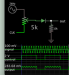
Here's an experimental simulation along the lines of my post #5. A diode serves as the doorway.

By itself the audio signal cannot pass through the diode, until mixed with a control voltage of sufficient level to overcome the diode threshold. Output is AC riding a DC voltage.

signal 100mV pushed through diode during control 2V.png
 

The datasheet of the obsolete TDA7052A power amplifier shows that it has a DC volume control that has a MUTE function. The TDA7052A ICs sold online might be fakes.
 

Status
Not open for further replies.

Similar threads

Part and Inventory Search

Welcome to EDABoard.com

Sponsor

Back
Top