+ Post New Thread
Results 21 to 29 of 29
-
12th November 2019, 22:16 #21
Awards:
- Join Date
- Apr 2014
- Posts
- 16,081
- Helped
- 3642 / 3642
- Points
- 79,217
- Level
- 68
Re: current-mode boost converter UC3845
Hi,
Datasheet says:
PCB Layout Considerations
To achieve best performance from an LT3782 circuit, the
PC board layout must be carefully done. For lower power
applications, a two-layer PC board is suffi cient. However,
at higher power levels, a multiplayer PC board is recom-
mended. Using a solid ground plane under the circuit is
the easiest way to ensure that switching noise does not
affect the operation.
In order to help dissipate the power from MOSFETs and
diodes, keep the ground plane on the layers closest to the
layers where power components are mounted. Use power
planes for MOSFETs and diodes in order to improve the
spreading of the heat from these components into the
PCB.Please don´t contact me via PM, because there is no time to respond to them. No friend requests. Thank you.
-
13th November 2019, 01:22 #22
- Join Date
- Aug 2015
- Location
- Melbourne
- Posts
- 1,955
- Helped
- 714 / 714
- Points
- 11,947
- Level
- 26
Re: current-mode boost converter UC3845
turn on your fets slower to reduce radiated noise - try 33 ohm for starters ...
-
Advertisement
-
13th November 2019, 07:41 #23
- Join Date
- Sep 2008
- Location
- cambridge
- Posts
- 6,954
- Helped
- 509 / 509
- Points
- 33,473
- Level
- 44
Re: current-mode boost converter UC3845
pcb design as attached
-
Advertisement
-
13th November 2019, 09:56 #24
- Join Date
- Aug 2013
- Posts
- 61
- Helped
- 0 / 0
- Points
- 1,416
- Level
- 8
Re: current-mode boost converter UC3845
thank you all
can i use pcb trace as shunt resistor?i need two 0/008 ohm resistor for current sensing.can i use 10mm length and 0/8mm width trace(0/008 ohm resistance and 0/4 watt losses) as current sense resistor?
-
Advertisement
-
16th November 2019, 20:34 #25
- Join Date
- Sep 2008
- Location
- cambridge
- Posts
- 6,954
- Helped
- 509 / 509
- Points
- 33,473
- Level
- 44
Re: current-mode boost converter UC3845
Sorry no its temperature dependent.
-
19th November 2019, 09:15 #26
- Join Date
- Sep 2019
- Posts
- 30
- Helped
- 2 / 2
- Points
- 207
- Level
- 2
Re: current-mode boost converter UC3845
i made this circuit with all the components used instead of the current sense resistor
at the source pin of the the mosfet. wound the inductor choke myself. the circuit input is 9vdc
and output is 48vdc but the trimmer indicated in the diagram when connected to pin # 2-Vfb of uc3843
the oscillator stops. when disconnect from pin # 2 start oscillating give output of 48vdc.
i don't know the reason why the oscillator stops when trimmer connect with Vfb with no output voltage.
- - - Updated - - -
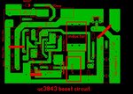
this is the PCB layout of the boost converter circuit. with trimmer not working.
-
20th November 2019, 20:35 #27
- Join Date
- Aug 2015
- Location
- Melbourne
- Posts
- 1,955
- Helped
- 714 / 714
- Points
- 11,947
- Level
- 26
Re: current-mode boost converter UC3845
too few volts into pin 2 perhaps? it is designed to see 2v5 from the output divider at all times ....
a soft start ckt would be a good idea too ...
-
21st November 2019, 08:45 #28
- Join Date
- Sep 2019
- Posts
- 30
- Helped
- 2 / 2
- Points
- 207
- Level
- 2
Re: current-mode boost converter UC3845
with Vout = 48vdc. if the trimmer is set to the bottom then the voltage at Vfb = 3.1 volt.
for Vfb = 2.5v by setting the trimmer at the bottom mean 10k + 4.7k = 14.7k in series with 0.8k.
but i want to change the output voltage to 14vdc using the trimmer which is not working.
-
Advertisement
-
21st November 2019, 09:53 #29
- Join Date
- Aug 2015
- Location
- Melbourne
- Posts
- 1,955
- Helped
- 714 / 714
- Points
- 11,947
- Level
- 26
Re: current-mode boost converter UC3845
you cannot have Vout < Vin due to the diode - you need to have a load on the o/p to test properly ...
+ Post New Thread
Please login