Continue to Site
Follow along with the video below to see how to install our site as a web app on your home screen.
Note: This feature may not be available in some browsers.
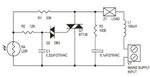
It should work and control an INCANDESCENT light so it gets brighter as less light falls on the LDR. Do not try to use it with low energy lamps as most are not dimmable. Beware that the whole circuit is 'live' so all parts of it must be insulated from being touched. Also try to keep the LDR away from light emitted by the lamp.
Brian.
")
I have cfl and led lamps
The circuit is designed for dimming. It is using phase control by a triac to reduce the effective voltage to a regular lamp. Both LED and CFL lamps have built in drivers that are resistant to voltage change. So CFL and LED lamps will not work in this circuit.
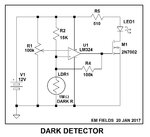
You can make a new design to turn lamps on and off using a set threshold of ambient light. Such a circuit will work with CFL and LED lamps.
Better search for a on-off circuit for light control (similar to ones used for control of street lights).
The relay current is depedent on the light level, obviously the contacts will make or break suddenly but if the coil current is marginal there is a risk of them arcing...
The transistors should be NPN. The circuit should work but it still has soft operating point. The relay current is depedent on the light level, obviously the contacts will make or break suddenly but if the coil current is marginal there is a risk of them arcing. Note that the input capacitor MUST be rated for full AC line voltage and I would advise you add a fuse in series with it. If the value is wrong or the capacitor fails it will cause catastrophic failure of the other components.
Brian.
What is the suitable rated current for the series fuse ?