Continue to Site

Welcome to EDAboard.com

Welcome to our site! EDAboard.com is an international Electronics Discussion Forum focused on EDA software, circuits, schematics, books, theory, papers, asic, pld, 8051, DSP, Network, RF, Analog Design, PCB, Service Manuals... and a whole lot more! To participate you need to register. Registration is free. Click here to register now.

[SOLVED] filtering a output of xor-ed signal

Status
Not open for further replies.

tarunkumartars

Newbie level 5
Joined
Oct 15, 2019
Messages
8
Helped
0
Reputation
0
Reaction score
0
Trophy points
1
Activity points
65
Hello ,

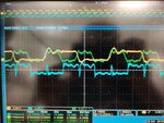
I have two signal yellow and green which i'm doing an xor operation with both and now i get blue signal as an output but the problem is it has a spikes as you can see in every half period. could someone help me in removing that or any ideas?
IMG-20191028-WA0000.jpg

P.S i'm just playing with gates and i wanted to see if the online simulation and theoretical results matches with my hardware setup which aren't matching. And here the BLUE signal is my final output

thank you
 

You have discovered the reason for using synchronous (clocked ) signals. When you have both signals transitioning simultaneously, there will be points in time where they are both interpreted as ‘ones’ or ‘ zeroes’ generating those glitches you see. Your circuit is working exactly as it should, although not like you want.
 

Yeah. Do you have any idea of removing that glitches as now my frequency is changed because of glitches!
Thank you
 

Yeah. Do you have any idea of removing that glitches as now my frequency is changed because of glitches!
Thank you
You can't remove the glitches, that is how combinational logic works. Besides across temperature, different lots of parts, and voltage you will have different timing and a different glitch behaviour. If you don't want glitches then make the design synchronous.
 

Depending on your design, those glitches may not be a problem at all. Or they may. You don't tell us anything about your design other than there's an XOR in it.
 

Depending on your design, those glitches may not be a problem at all. Or they may. You don't tell us anything about your design other than there's an XOR in it.

They just did tell us, they are using the output as a clock. You can see it is a 90 degree phase shifted version of the yellow clock. Though they would be better off using a D-Flip-flop and a inverter to clock the yellow data through the flip-flop using the falling edge of the green clock, which would then produce a "clean" (registered) blue clock.
 

They just did tell us, they are using the output as a clock. You can see it is a 90 degree phase shifted version of the yellow clock. Though they would be better off using a D-Flip-flop and a inverter to clock the yellow data through the flip-flop using the falling edge of the green clock, which would then produce a "clean" (registered) blue clock.

could you explain a bit more clear, couldn't get the way u did using d flip flop?
thank you
 

Hi,

I agree with the others.

Maybe a solution: (not nice, but maybe useful)
Low pass filter the output of the XOR with an RC. Tau about 30ns. (maybe with this you can ged rid of the glitches)
Then use a buffer or schmitt trigger to make a clean square wave.

Klaus
 

could you explain a bit more clear, couldn't get the way u did using d flip flop?
thank you

This is what I mean
Code:
       _______         _______         _______         _______ 
clk1 _|       |_______|       |_______|       |_______|       
       ___     ___     ___     ___     ___     ___     ___    
clk2 _|   |___|   |___|   |___|   |___|   |___|   |___|   |___
           ___ ___         ___ ___         ___ ___         ___
xor  _|___|   |   |___|___|   |   |___|___|   |   |___|___|  gives glitches on every transition
            _______         _______         _______         __
clko ______|       |_______|       |_______|       |_______|  


using a D-FF with falling edge clock (the o on the clock is an inverter)
          _____
         |     |
clk1 ----|D   Q|---- clko
         |     |
clk2 ---o|>    |
         |_____|

- - - Updated - - -

Hi,

I agree with the others.

Maybe a solution: (not nice, but maybe useful)
Low pass filter the output of the XOR with an RC. Tau about 30ns. (maybe with this you can ged rid of the glitches)
Then use a buffer or schmitt trigger to make a clean square wave.

Klaus

This is an ugly solution that will result in significant duty cycle distortion and latency, but if that doesn't mater then it will work, but will require more components. 1 Resistor, 1 capacitor, and a schmitt trigger buffer. I wouldn't use a regular buffer as the Tau of 30ns is probably still to low to filter out all the runt pulses to not have them get seen by a regular buffer. The schmitt trigger will allow you to turn the xor output into a sine wave before converting back to a clock, but this design will have a large amount of variable latency that will change over voltage, temperature, and components.

If what you are clocking doesn't care about the quality of your clock then go ahead and try the RC filter method. If you have a handy D-FF with negative edge clock input then the way I suggest will give you a far better result.
 
Status
Not open for further replies.

Part and Inventory Search

Welcome to EDABoard.com

Sponsor

Back
Top