Welcome to our site! EDAboard.com is an international Electronics Discussion Forum focused on EDA software, circuits, schematics, books, theory, papers, asic, pld, 8051, DSP, Network, RF, Analog Design, PCB, Service Manuals... and a whole lot more! To participate you need to register. Registration is free. Click here to register now.
I need to switch some ressitors into a resistance network, but this means I have a resistive load on my source as well as drain of the fet. Can I do this??
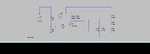
see attachment
Yes I'm using LTspice and it works perfectly on the simulation. I know there is no minimum source drain current , just wanted to confirm I'm not missing anythnig silly really.
R8 and R9 are way too low in value as each resistor will be dissipating 10 watts.
Change then to something like 10k ohms.
If you want to determine the power dissipated in a device after a transient simulation, just roll the cursor over the device will holding the ALT key until the thermometer symbol appears, and then left click.
All those dangling nodes and wires makes for a messy schematic.
Just remove them with the cut (scissors) tool.
Hi Zapper,
Yes I know they are too low. The reason for the circuit is I'm using a switch with a min wetting current of 10mA. the switch contacts are between R8and R9 . ,so i can make them a value that say delivers 20mA .
I was just playing with the values of R8 and R9 . I just need to ensure that the potential devided is more than the min Vth for the fet
If you had the supplies handy, an analog switch IC would
probably be your better bet. Your network values are high,
analog switches can be had below 10 ohms per channel.
Far lower standby current than what you've got now.
Yes I know they are too low. The reason for the circuit is I'm using a switch with a min wetting current of 10mA. the switch contacts are between R8and R9 . ,so i can make them a value that say delivers 20mA .
I was just playing with the values of R8 and R9
V_th is where the MOSFET starts to get conductive.. maybe just a couple of microamperes. (read datasheet).
To safely make a MOSFET low ohmic you need V_GS way above V_th. (also read datasheet)
This site uses cookies to help personalise content, tailor your experience and to keep you logged in if you register.
By continuing to use this site, you are consenting to our use of cookies.