Continue to Site

Welcome to EDAboard.com

Welcome to our site! EDAboard.com is an international Electronics Discussion Forum focused on EDA software, circuits, schematics, books, theory, papers, asic, pld, 8051, DSP, Network, RF, Analog Design, PCB, Service Manuals... and a whole lot more! To participate you need to register. Registration is free. Click here to register now.

"Current" controle is a big issue using ClassD ?

Status
Not open for further replies.

Hasan2017

Member level 4
Joined
Oct 23, 2017
Messages
76
Helped
0
Reputation
0
Reaction score
0
Trophy points
6
Activity points
831
Hi there,

I think people who works in 'Analog or Power electronics" understand this issue.
I am having a project on, "3 phase power Calibrator"

Like me previous post I was trying to go with a ClassAB for current and voltage amplifier.https://www.edaboard.com/showthread.php?386525-Lets-take-a-look-on-a-linear-amplifier

Comparable study shows, ClassAB is less suitable than ClassD.
ClassD is a voltage source device, so current transformer may not be use, https://www.diyaudio.com/forums/class-d/343198-class-amplifier-suitable-60hz-potential-transformer.html#post5927022

I think potential transformer can be use with ClassD, https://www.element14.com/community/thread/73845/l/classd-amplifier-for-transformer


Since my project need to get Current transformer output, kindly suggest me what should I do.
I'am not sure with this solution, https://e2e.ti.com/support/motor-drivers/f/38/t/848028
 

Hi,

Could you please list all your requirements. Searching through a couple of posts/threads to find out what you want to achieve needs a lot of time.
Voltage range, current range, frequency range, waveform .... and so on
And an additional draft could also help to clarify things.

It's not clear what you mean by "ClassAB for current and voltage amplifier"
Independent of amplifier class ... the (filtered) output will follow the input signal and will amplify voltage as well as current.
The filtered output of a class D should be identical to the output of a class AB (except side effects like distortion, noise, phase shift...)
This is true for voltage as well as current.
The difference between both is how the signal is generated within the amplifier... and the expected power dissipation.

For example: in an AB amplifier all reactive load power needs to be dissipated as heat, with an class D amplifier it is pused between load and DC supply path of the amplifier.
Connecting a C to an AB amplifier causes much heating ... but with a class D amplifier the heating is low.
The average current in a class D DC supply is low (but the AC current, RMS may be fairly high)

*****
Maybe you want a "current regulation loop" (which ideally has infinite output impedance)
.. or a "voltage regulation loop" (which ideally has zero output impedance)
It should be obvious that you can't have both at the same time.

Klaus


Thank you for such "huge" knowledge.
It works indeed.

I beg pardon if its hard to go with.


Now let us move to a individual solution on for "Current"( what you have said loop)

Requirments are modified here:

1. The amp input should be plus and minus 7volt AC, 45-65Hz( 1 Hz has been converted to 1024)
2. Amp operating voltage should be more or less 24v.

3. Only single channel "current" signal should be amplify on both side.
4. 7.5 ohm load.
5. Output should be 16.5 V/1.5 A. 25 Watt.

6. SC protection and current sensing capabilities.

7. CT, current transformer primary winding has to be 16.5 V/1.5 A(Amplified signal), secondary should have 4.125v/6A output!
 

Hi,

Sadly still there is a lot unclear to me.
I strongly recommend to draw a draft of what you want to achieve. Some kind of block diagram where we can see signal flow, amplifier filter (if any), feed back (if any), and so on.

Even the most important is unclear to me: What's your target...

Now let us move to a individual solution on for "Current"( what you have said loop)
Does this mean you want to build a "current amplifier"? ... where with varying load resistance it automatically adjusts output voltage to get constant output current? = amplifier with "current" as feedback value?

1. The amp input should be plus and minus 7volt AC, 45-65Hz( 1 Hz has been converted to 1024)
Waveform = sine?

2. Amp operating voltage should be more or less 24v.
DC? Single supply?
--> If yes, then this means you need full bridge output topology.

3. Only single channel "current" signal should be amplify on both side.
What do you mean by "single channel" and "both side"?

5. Output should be 16.5 V/1.5 A. 25 Watt.
If sinewave: do you mean 16.5V RMS?
This equals to +/-23.33V.
--> This would mean a too low margin to a 24V DC supply.

25W on an ohmic load of 7.5 ohms gives 13.69V RMS and 1.83V RMS. How does this comply with your 16.5V / 1.5A?

6. SC protection and current sensing capabilities.
This could mean a lot.
Short circuit protection. What do you want to protect? Mainly the load, or mainly your amplifiers output stage?
How should it work? Like a fuse ... to stop operation until the user resets? In hickup mode ... in a way that it stops operation, but automatically retries? Just as limiter ... how fast? Before or after the filter?

CT, current transformer primary winding has to be 16.5 V/1.5 A(Amplified signal), secondary should have 4.125v/6A output!
I'm also confused with this. A CT usually has no "input voltage specification" .. because it just "sees" the current.
And usually the output current is much less than the input current (let's say in a range of 5mA ... 100mA depending on type), but in your case it is the other way round.
Did you go through usual CT datasheets and CT application notes? If not, please do this to understand operation.

Sorry for that many questions.

Klaus
 

Sadly still there is a lot unclear to me.
I strongly recommend to draw a draft of what you want to achieve. Some kind of block diagram where we can see signal flow, amplifier filter (if any), feed back (if any), and so on.
Take a look my previous work in form of ClassAB. Darlington pair brings current.
I need exactly those parameters to amplify my signal.
current_ab_amp.jpg


Even the most important is unclear to me: What's your target...
Overcome "heating and avoiding crossover distortion"

Does this mean you want to build a "current amplifier"? ... where with varying load resistance it automatically adjusts output voltage to get constant output current? = amplifier with "current" as feedback value?
See the dia gram kindly. Yes its has feedback, shunt, high frequency cancelation.


Waveform = sine?
Sure

DC? Single supply?
--> If yes, then this means you need full bridge output topology.
May be. Some one suggest me this kind of application.
bridge_idea.png

What do you mean by "single channel" and "both side"?
From my STM 32 board 2 channel current and voltage signal, comes from D8812 may be.

If sinewave: do you mean 16.5V RMS?
This equals to +/-23.33V.
--> This would mean a too low margin to a 24V DC supply.
May be peak to peak 16.5V( just after amplification)
DC supply must be more or less 24v.

25W on an ohmic load of 7.5 ohms gives 13.69V RMS and 1.83V RMS. How does this comply with your 16.5V / 1.5A?
After amplification. 25W may not currect.

This could mean a lot.
Short circuit protection. What do you want to protect? Mainly the load, or mainly your amplifiers output stage?
How should it work? Like a fuse ... to stop operation until the user resets? In hickup mode ... in a way that it stops operation, but automatically retries? Just as limiter ... how fast? Before or after the filter?

1. Low frequency and high frequency phase shifts caused by a transformer will occur if the transformer is inside the negative feedback loop (when the output of the transformer provides the negative feedback). Then the amplifier must be compensated for these phase shifts.A transformer causes a phase shift at low frequencies caused by its inductance.

2. A product with a Class-D audio power amplifier (APA) driving an output transformer with inadequate low-frequency performance may shut down when its output is stepped from zero to maximum at the start of a sine cycle. Shutdown is triggered by short circuit protection (SCP), after the first half cycle of the sine output. The root cause is saturation of the transformer core


I'm also confused with this. A CT usually has no "input voltage specification" .. because it just "sees" the current.
And usually the output current is much less than the input current (let's say in a range of 5mA ... 100mA depending on type), but in your case it is the other way round.
Did you go through usual CT datasheets and CT application notes? If not, please do this to understand operation.


Well said. CT gives maximum 6A.
Firmware code will allow us to change the range!
 
Last edited:

Hi,

OK, some things are clarified.
I need exactly those parameters to amplify my signal
So if you need exactly this .... why don't you just replace the AB stage with a class D stage with filter?

Btw: you say your input frequency is 45Hz ...65Hz, but I see your input high pass filter cutoff freqency is about 160Hz.

******
I see you really want "current regulated output". Good to be clarified.

Your AB circuit has symmetrical power supply...+/-24V

Yes its has feedback,
The question was: "current feedback" vs "voltage feedback". But it's clear now.

For you. But there are milllion applications that don't use sine shape.

May be. Some one suggest me this kind of application.
OK. Full bridge class D. For sure you know this schematic is not complete. The whole Mosfet gate control is missing.

I recommend a ready to buy audio class D amplifier IC, where you can modify / add the current feedback path.

And now I see your transformer. This is no "classical CT". It rather is a classical power transformer.
A classical CT has sinle turn primary winding and high turn count secondary winding. For sure there may be others.
Classical CT's are not meant to transfer power...and don't need to be efficient.

Any power transformer will transform voltage as well as current. In your case you just focus on current.
--> You need to use a (quite usual) power transformer.

From my STM 32 board 2 channel current and voltage signal, comes from D8812 may be.
I completely don't understand what this means...and how it is involved in class D problem..

A transformer causes a phase shift at low frequencies caused by its inductance.
I only partly agree.
In your case what counts is the pri--> sec phase shift, not the V-->I phase shift.
For the pri-->sec phase shift only the (small, series) stray inductance counts. Phase shift is small, but may increase with load current.
(For V-->I phase shift the big parallel inductance counts, phase shift will decrease with load current)
Pri--> sec phase shift is low. Depending on transformer in the low microseconds. For sure you need to take care of it to ensure amplifier stability. I recommend that your circuit operates only to a given frequency in "current feedback mode" and then turns over to "voltage feedback mode" to ensure stability.

Saturation: it's just a problem of a properly dimensionated transformer.
If you don't need to go close to the "saturation limit" (cost, size), then just leave enough headroom.

I'll be absent for a couple of hours now...leaving room for others to post ;-)

Klaus
 

So did we agree you're looking for a current regulated class-D amplifier? Any specs for distortion, accuracy or bandwidth (I see now ~60hz?)


It's conceptually easy to wrap a voltage mode controlled amplifier in a current regulation loop, but it's very hard to get good performance if the load has wide variation. Current loop gain in a voltage mode supply depends on load and approaches infinity into a short circuit. Thus the loop must have limited gain if it's going to be stable into a short and would have poor performance into other loads.


You'll find almost no resources on "current mode controlled" class-D but the good news is that standard buck converter techniques work fine (peak, hysteric, average) in general with a class-D full bridge. But you're probably on your own implementing it (no controllers that I'm aware of).
 

Re: "Current" controle is a big issue using ClassD ?

Mind blowing response.
Really you help me a lot!


So if you need exactly this .... why don't you just replace the AB stage with a class D stage with filter?
Dont you mean input high pass filter.
Lets post a basic classd dia gram. Do you want me to follow this basic?

classD.PNG


Btw: you say your input frequency is 45Hz ...65Hz, but I see your input high pass filter cutoff freqency is about 160Hz.
Well noticed! In case of current, R1 and C1 has contribution for attinuation.
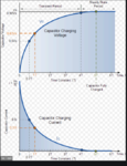
Since AC signal, capacitive impedance is considarable, RC time conStant facts.

c_charging.PNG


A
nd now I see your transformer. This is no "classical CT". It rather is a classical power transformer.
A classical CT has sinle turn primary winding and high turn count secondary winding. For sure there may be others.
Classical CT's are not meant to transfer power...and don't need to be efficient
.

Its a toroidal core, you know it has some benifit.
Take a look datasheet.CT_specification.PNG

I only partly agree.
In your case what counts is the pri--> sec phase shift, not the V-->I phase shift.
For the pri-->sec phase shift only the (small, series) stray inductance counts. Phase shift is small, but may increase with load current.
(For V-->I phase shift the big parallel inductance counts, phase shift will decrease with load current)
Pri--> sec phase shift is low. Depending on transformer in the low microseconds. For sure you need to take care of it to ensure amplifier stability. I recommend that your circuit operates only to a given frequency in "current feedback mode" and then turns over to "voltage feedback mode" to ensure stability.

Well said, power conversion in terms of voltage and current.
Phase shift is a reason. Now lets take a look how amplifiers conduction phase varies, does not it relavant ? How slow transformer can pick signal!
Classes-of-Power%20-Amplifiers.png
Could you kindly see the "Shunt". How does it work here!

"If a transformers primary winding was connected to a DC supply, the inductive reactance of the winding would be zero as DC has no frequency, so the effective impedance of the winding will therefore be very low and equal only to the resistance of the copper used. Thus the winding will draw a very high current from the DC supply causing it to overheat and eventually burn out, because as we know I = V/R "

- - - Updated - - -

So did we agree you're looking for a current regulated class-D amplifier? Any specs for distortion, accuracy or bandwidth (I see now ~60hz?)


It's conceptually easy to wrap a voltage mode controlled amplifier in a current regulation loop, but it's very hard to get good performance if the load has wide variation. Current loop gain in a voltage mode supply depends on load and approaches infinity into a short circuit. Thus the loop must have limited gain if it's going to be stable into a short and would have poor performance into other loads.


You'll find almost no resources on "current mode controlled" class-D but the good news is that standard buck converter techniques work fine (peak, hysteric, average) in general with a class-D full bridge. But you're probably on your own implementing it (no controllers that I'm aware of).

Great !
Good observation.

This is one reason that my system has a voltage gain much too small at only 1/14 x [1+ (4.7k/1k)]= 0.41 times without a load and less when there is a load.
Good news is 'it works fine" and we can make money for sure but with 'poor quality".

some said "You don't want to drive a loudspeaker with music you want to drive a transformer with a 50/60Hz sine wave. The 363
PHP:
7http://www.ti.com/lit/ds/slus283/slus283.pdf
is going to do that with a current, 2A RMS, sine wave, as opposed to a voltage one. It is very likely that if you try to short circuit it either deliberately or as a result of the transformer doing something wrong it will just sit there happily driving it with a 2A RMS sine wave and nothing else will happen."

It cant be control by my system.TI has similar one, https://www.ti.com/product/DRV8412


Could you kindly suggest me any standard buck converter techniques (peak, hysteric, average)?
 
Last edited:

Hi,

Dont you mean input high pass filter.
No, output low pass filter. Connected to the output if tge class D amplifier to make the digital PWM signal a smooth analog signal.
You need the filter, because you need the current feedback signal from the analog signal.
I see no way to get useful current feedback from the PWM pulses.
Lets post a basic classd dia gram. Do you want me to follow this basic?
Why do you bother with complicated class D block diagranms, when there are ready to buy class D amplifiers.
They have analog input and speaker output...the internals are not much of interest..as long as the specificatiin meets your requirements.
Then just replace your AB amplifier with the class C amplifer and filter.

Phase shift is a reason. Now lets take a look how amplifiers conduction phase varies, does not it relavant ? How slow transformer can pick signal!
I can't see what the amplifier classes have to do with the conduction phases.
And what all this has to do with your application.

As written above: just replace the AB amplifier.

Klaus
 

No, output low pass filter. Connected to the output if tge class D amplifier to make the digital PWM signal a smooth analog signal.
You need the filter, because you need the current feedback signal from the analog signal.
I see no way to get useful current feedback from the PWM pulses.
Okay. For the previous ClassAB I want to remember that "The first difference between voltage feedback and current feedback—the input impedance of current feedback op-amp inputs is very different. Because the inverting input has low impedance"


Then just replace your AB amplifier with the class C amplifer and filter.
Not sure what you wanna say!


As written above: just replace the AB amplifier.
Okay fine.
Dont you think, this kind of circuit I could simulate ? May be simulation point will over!:thumbsdown:
(For the time being, forget about voltage,power and current rating)
400w-claas-d-amplifier-schematic-irs2092-class-d-amplifier-protection.png
 

Hi,

apperantly you mix things.
* nobody talks about "current feedback OPAMPs"
* but you want a current regulation loop, thus you need to feedback the value of the load current somehow. --> current feedback.

Dont you think, this kind of circuit I could simulate
I don´t know if this can simulatate, but I gues: yes.

In my eyes you overcomplicate things.
Why do you build your class D amplifier with that many discrete parts, when there are simple, cheap, ready to buy IC´s.
And the additional benefit of the ICs is that they usually include some useful features like: DC suppression, soft start up, overcurrent protection, overheat protection....
Just go to a good distributor (or manufacturer) of your choice and do a search for audio class D amplifier ICs.

Not sure what you wanna say!
Maybe you want to spend some time to draw an overview of your system: difference amplifier, class AB amplifier, current measurement, load.
then replace the AB amplifier with the class D amplifier:
The result should be: difference amplifier, calss D amplifier with filter, current measurement, load.

But for sure you are free to build all this with (maybe hundred) discrete parts. It´s your choice. And there´s nothing wrong with it, but I would no go this way.

Klaus
 

I wouldn't simulate that circuit. Start with a much simpler model. For a class-D amp the output filter will dominate the power stage transfer function at least until you approach the switching frequency. So in simulation you can start with just an ideal linear amplifier followed by your planned class-D output LC filter. That's how I'd start for the purposes of analyzing control schemes.
 

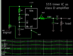
Simple class D amplifier made from 555 timer IC. Apply audio signal to pin 5. Varying voltage at pin 5 alters duty cycle.
Incoming signal needs to be shifted to positive polarity.

555 class D amplifier LCC filter load 50 ohm gets AC.png

It's practical to set a faster carrier frequency. CD quality is 41kHz. You get better fidelity, and you can use a lower value inductor.
 

Current mode control IME is about load-step response.
Class D doesn't have load steps per se, only as much as
output voltage dictates against the fixed(ish) load.

What benefit does anyone claim for current mode control
in a Class D amplifier application, vs. simple voltage mode
(or even open loop direct analog-to-PWM)?
 

Well it seems the OP wants to control current: "Since my project need to get Current transformer output"...and current mode control is a great way to do that.

Generally current mode control transforms a second order control problem into a first order control problem (or two) possibly making it easier to compensate the system in the face of unpredictable loads. And it gracefully handles faults.
 

Re: "Current" controle is a big issue using ClassD ?

Thank you. Could you show me a suitable circuit diagram?

- - - Updated - - -

Current mode control IME is about load-step response.
Class D doesn't have load steps per se, only as much as
output voltage dictates against the fixed(ish) load.

What benefit does anyone claim for current mode control
in a Class D amplifier application, vs. simple voltage mode
(or even open loop direct analog-to-PWM)?

Well, nicely pick a point. Post a in general load step response with a easy circuit.

- - - Updated - - -

It's practical to set a faster carrier frequency. CD quality is 41kHz. You get better fidelity, and you can use a lower value inductor.
Can you change its frequency range to 45-60Hz? Suggest me a slower medium. Read the post from top to bottom kindly.
 

Re: "Current" controle is a big issue using ClassD ?

Can you change its frequency range to 45-60Hz?

Yes, my simulation illustrates the concept in a simple circuit.
Adjust component values to yield your desired range of frequencies. Add a half-bridge if desired. Make the power supply single-ended or bipolar as desired. Etc.
 
Status
Not open for further replies.

Similar threads

Part and Inventory Search

Welcome to EDABoard.com

Sponsor

Back
Top