+ Post New Thread
Results 1 to 4 of 4
-
15th October 2019, 23:15 #1
- Join Date
- Oct 2019
- Posts
- 2
- Helped
- 0 / 0
- Points
- 26
- Level
- 1
L293d - Input Voltage (motor operation)
I have made project " DTMF Based Land Rover ".
The whole circuit is working in usual manner. The voltage at arduino output pins is 3.46 volts.
And pin no 16 and 8 are Vcc of L293d respectively
So they are connected to 6V.
When arduino output is driven into motor drive ic L293d, motors connected at output of ic is not rotating. So can anyone tell me why the motor is not rotating.
( According to me it can be because of low voltage at input pins of L293d. So can anyone suggest how can i increase the voltage at input pins )
If this is due to some different reason, kindly please help me with solution.
-
Advertisement
-
16th October 2019, 00:49 #2
Awards:
- Join Date
- Apr 2014
- Posts
- 16,051
- Helped
- 3635 / 3635
- Points
- 79,089
- Level
- 68
Re: L293d - Input Voltage (motor operation)
Hi,
According to me it can be because of low voltage at input pins of L293d.
It clearly says every input voltage above 2.3V is valid HIGH level.
Better than long textual description is a picture.
--> please show is a schematic of your circuit.
E.g. you don't talk about GND .. or how the motor is connected ... or which motor you are using...
KlausPlease don´t contact me via PM, because there is no time to respond to them. No friend requests. Thank you.
1 members found this post helpful.
-
Advertisement
-
16th October 2019, 15:22 #3
- Join Date
- Oct 2019
- Posts
- 2
- Helped
- 0 / 0
- Points
- 26
- Level
- 1
Re: L293d - Input Voltage (motor operation)
Thankyou Klaus for your quick response.
I have read the datasheet and changed my IC for the third time but the problem is same.
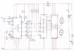
Circuit diagram
The motor i am using is 6V DC geared motor
My battery is 6V , 4.5Ah
( Once i was testing my IC L293d and Vcc and GND where connected as per requirement. And i connected input pins directly to Vcc and GND according to input combinations. I left pin no 1 and 9 open which are enable pins of channel 1-2 and 3-4. Still the motor started rotating. I was totally shocked after seeing this. Can you explain me this one also)
-
Advertisement
-
16th October 2019, 22:34 #4
Awards:
- Join Date
- Apr 2014
- Posts
- 16,051
- Helped
- 3635 / 3635
- Points
- 79,089
- Level
- 68
Re: L293d - Input Voltage (motor operation)
Hi,
. I was totally shocked after seeing this. Can you explain me this one also)
Don't leave any inputs floating, neither at digital ICs nor at analog ICs...as long as it is not mentioned otherwise in the datasheet.
Floating means the voltage level is undefined, it may be true Low, it may be true High, it may be in the "unallowed" area between Low and High (causing increased supply current), it may even oscillate.
Even when there is no notice in the datasheet you must not leave them floating.
But in this case the datasheet clearly mentiones:
Provide a 5-V supply to VCC1 and valid logic input levels to data and enable inputs.
Datasheet says:
Bypass capacitors of 0.1 uF or greater should be used at VCC1 and VCC2 pins.
Also you need proper electrolytics bulk capacitors. They need to store the energy of the inductive motor when switched Off.
An overvoltage suppression is also a good idea.
Extra capacitors are needed for the 7404 and the MT8870.
Your PCB should contain a solid GND plane. Don't use a breadboard.
KlausPlease don´t contact me via PM, because there is no time to respond to them. No friend requests. Thank you.
+ Post New Thread
Please login