Continue to Site

Welcome to EDAboard.com

Welcome to our site! EDAboard.com is an international Electronics Discussion Forum focused on EDA software, circuits, schematics, books, theory, papers, asic, pld, 8051, DSP, Network, RF, Analog Design, PCB, Service Manuals... and a whole lot more! To participate you need to register. Registration is free. Click here to register now.

Buck converter vs buck-boost converter

Status
Not open for further replies.

pragash

Advanced Member level 2
Joined
Jul 4, 2005
Messages
512
Helped
64
Reputation
128
Reaction score
59
Trophy points
1,308
Location
Oakland
Activity points
4,939
which one is more power efficient? Buck converter or buck-boost converter?

some of you may say its depends on your application. if lets say i can use either one. which one will be more power efficient and why?
 

Either one is theoretically 100% efficient.

It completely depends on the system architecture.

That said there is a reason there are more bucks than boosts in most system. It's typically more efficient to deliver watts with higher voltage busses then step down to lower voltages near the point of load (POL).


EDIT: Sorry I missed the 'buck' in 'buck-boost'. Buck-boosts are also theoretically 100% efficient but have a negative quality that power essentially flows in a circle from input, to the DC link caps, then out. Or another way to show it is this:
Buck converter: Inductor/switch current equals output current
Boost converter: Inductor/switch current equals input current
Buck-boost converter: Inductor/switch current equals input+output current.

The input+output current reality creates some additional losses.

4 switch buck converters alleviate that problem (by operating in either boost or buck mode at any particular moment) but at the cost of a second stage.


So always choose buck unless you really need the boosting capability.
 
Last edited:
thank you so much for the answer. any equation for efficiency or current draw in the Buck, Boost and buck-Boost converter? i will help me to understand the power loss even better. thanks.
 

No equation because like other switching topologies in theory it has perfect efficiency.

So also like other switching topologies calculating losses is tricky and depends on accurate information about all the components.

We just did a very wide range (60:1) 2-switch buck-boost that achieves 90% plus efficiency over much of that range.
 

boost converter usually has low side drive to the fet which is easier, buck converter needs a level shift driver or a P channel fet - more parts will affect efficiency - but either can be made very efficient
 
If
Vin > Vout - Use buck
Vin < Vout - Use Boost
If vout can be higher or Lower than Vin and automatic buck/boost switchover is required then use Buck-Boost.
Most of the buck-boost converters will have 4 MOSFETs integrated in package and less current rating compared to Buck/Boost with same footprint.
If there is an option to use Buck or Buck-Boost --> Go ahead and use BUCK only.
 

A flyback is also a buck-boost ( the original in fact )

- - - Updated - - -

as is a Sepic
 

In Buck-Boost you will tend to get more switching losses as your fet off state voltage will gernerally be higher.
Also, the rms fet current will be higher with a buck-boost.
 
you may get the same total losses as only one fet to control and one o/p diode - plus far easier control - less time to build and get going ...
 
  • Like
Reactions: pragash and treez

    T

    Points: 2
    Helpful Answer Positive Rating

    pragash

    Points: 2
    Helpful Answer Positive Rating
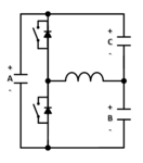
I had wanted to post this. This is how I visualize the 2-switch buck-boost and its relationship to boost and buck - they're all the same just different inputs and outputs (and sometimes fets replaced with diodes).

buck-boost.PNG

Buck: A->B
Boost: B->A
Buck-Boost : B->C (or vice versa) through A.

The 'through A' part is essentially what hurts efficiency. As well as the B+C voltage stress.

Note that because these typologies are in-fact identical you can use off-the-shelf buck converters as buck-boost:
https://www.ti.com/lit/an/slva514b/slva514b.pdf
 

respectfully - you not bucking or boosting from input to output... a common ground is also often assumed which this ckt cannot supply
 

When you search 'Buck-boost' that's the circuit you get. The original question was about efficiency - it seems rather obvious a 4-switch buck boost is less efficient since in either mode it adds switches compared to buck or boost. Hence it seems reasonable the poster was thinking about this (though you never know).

My recent buck boost design had an isolated input so I attached it's (+) to system ground. Works fine.
 

That's exactly the circuit I was referencing. But take a closer look and you'll see your wikipedia diagram is the same topology as mine. Your diagram's input is my C, output is B, cap A is omitted (a mistake) and the straightforward diode/fet swap (making it non-synchronous).

But this confusion is why I came back to post that picture. The wikipedia diagram very poorly illustrates a couple things:
-The relationship of Vin to Vout (Vin- is Vout+ here, I.E. its inverting)
-The relationship to buck and boost (it's basically the same)
-How to lay it out: A is always the high frequency commutation loop and needs a bypass cap


Yes I agree a flyback is an isolated buck-boost and the flexibility the transformer offers alleviates potential ground reference issues.
 

cap A is there by virtue of B & C, i.e. cap A can be deleted if B & C are there ...
 

I doubt you'd ever lay out a switching supply without a bypass directly across the switch commutation loop.
 

Try the LT8705...this is a "bock or boost" converter........it acts as a buck if vin>vout, and acts as a boost of vout > vin

LT8705
https://www.analog.com/media/en/technical-documentation/data-sheets/8705ff.pdf

...If vin = vout then it does some weird kind of extra switching operation as it transitions between buck and boost....but still works fine

i think you should read about LT8705 and its app notes...as it answers your qu.....it basically belies the situation of buck or boost being in many ways (but not all) superior to buckboost
 

LT8705 is a lot of bits if you just want a low power converter

@ asdf44; I think the point is made - with good layout capA is not required ...
 

Theres also a two switch buckboost, which also has two diodes, which can serve if vout > or < vin.
I wont draw it, i am sure you can get it.
It has a ground referenced output.......ie the same ground as its input.

My favourite buckboost is the buckboost led driver with single low side fet, and leds referenced to vin.
 

you are referring to a cascaded buck + boost, 2 converters in one ...
 
  • Like
Reactions: treez

    T

    Points: 2
    Helpful Answer Positive Rating
Status
Not open for further replies.

Similar threads

Part and Inventory Search

Welcome to EDABoard.com

Sponsor

Back
Top