Continue to Site

Welcome to EDAboard.com

Welcome to our site! EDAboard.com is an international Electronics Discussion Forum focused on EDA software, circuits, schematics, books, theory, papers, asic, pld, 8051, DSP, Network, RF, Analog Design, PCB, Service Manuals... and a whole lot more! To participate you need to register. Registration is free. Click here to register now.

[SOLVED] Wiring of DC fans in Series

Status
Not open for further replies.

Xenobius

Member level 5
Joined
Feb 25, 2019
Messages
84
Helped
0
Reputation
0
Reaction score
0
Trophy points
6
Activity points
850
Hi I have an enclosure with a 30vdc power supply inside.
I would like to add some fans to keep things cooler inside however its much simpler to buy a 15vdc fan than a 30vdc fan.

So I figured if I connect 2 in series I would split the voltage and bob's-your-uncle as they say however a friend of mind pointed out that it might not be good since a fan is inductive not resistive...
How does (if) this affect the fans in series?

Thanks :)
 

Generally not a good idea but it depends on the actual fan design. Most low voltage DC fans do not draw a precise current and it quite likely goes up and down as the fan rotates. As a consequence, if you wire them in series there is a high likely hood that the voltage across each fan will vary considerably and will probably go out of specification. Also consider what would happen if one fan stalled or was jammed, it would try to take more current and the voltage across it would drop, that means more voltage across the remaining fan.

Brian.
 

Nothing is simple :D 7815 perhaps might solve the issue!
 

Yes, you can use two 7815 regulators to drop the 30V down to two 15V supplies but the drawback is they will almost certainly run very hot. They have to dissipate (voltage dropped * fan current) Watts so check what current the fans draw and do the calculation. If the result is more than about 0.25W you will need heat sinks on the regulators.

A 'dirty' way to do it is to use two 15V Zener diodes, one across each fan then connect them in series. If the fans draw identical currents the diodes will do nothing but they will help to balance the load by ensuring neither fan can have more the 15V across it. It isn't an ideal solution but it goes some way to helping.

Brian.
 
The current draw of small DC fans do indeed change with rotation. Additionally, you cannot expect the two devices to draw the exact same current, even if they are the same brand and model.

Bryan's zener recommendation is a cheap and simple way to prevent overvoltage conditions on the fans.
For safety margin, assume that worst case the zeners will have to carry at least 1/2 the fan current.

For instance, if the fan's are rated for 150 mA, assume that worst case the zener will cary 75 mA. Multiply it by 15 and and it will give you 1.125 watt. Use a 2 watt zener. Better safe than sorry.
 
Hi,

A power voltage divider could be made with two equal resistors, an NPN and a PNP...
Not very precise, but good enough for fans

Klaus
 
a 5W 16V zener across each fan will be the way to go, else a buck converter to 15V to run both of them in //.
 
I really like all the solutions with zeners and potential divider. I was thinking of using 15v fans because its half my supply however now its a different story. I have a bunch of fans I could use a voltage divider

R1R2V
10K (0.5w)39K (2w)23.88V @ 60mA
4k7 (2w)3k3 (1w)12.38V @ 70mA
10K (5w)2K2 (2w)5V @ 180mA
 
Last edited:

R's are fine - but extra power draw / loss and no guarantee of sharing at power up where fans can and do draw more than 5x the run current - and its pretty pulsed too...!

- - - Updated - - -

don't forget the fans will pull current and distort your calculations - esp at start ...
 

Hi

Try this:
* NPN, PNP, 2x R = 4k7

Wire it this way:
* 30V --> NPN_C
* NPN_E to PNP_E = 15V output
* PNP_C to GND
* resistors in series, one end to 30V, the other end to GND.
* resistors_center to NPN_B and PNP_B

Klaus
 

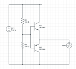
Something like so? So the resistors are just a 15v potential divider that are turning on the transistors but what limits it to 15v?

Fan.PNG
 

You are missing the fan connections and 100R is far too low in value, the resistors alone would dissipate 2.25W each!

What Klaus is suggesting is basically two emitter follower circuits, they have current gain but not voltage gain so whatever voltage you put on their bases from the potential divider will appear on their emitter pins and hence the fans. For it to work you still need the two near identical 15V fans in series as well. This and the Zener diode idea will work but they both have the same potential problem of one fan stalling and causing increased current through the other half of the circuit. To be safe, consider the situation where one fan goes completely short circuit and look what the power dissipation does in the other circuit across the other fan.

I'm not sure what the resistor values in post #8 are for, they don't make any sense to me. If you are thinking of simply using a series resistor to drop the fan voltage you should be careful to note the start-up current from stopped condition is usually far higher than the running current so the fan may start very slowly or not at all.

Brian.
 

Q4 is not needed - Q3 will dissipate, Ifan * 15V so be careful there ...
 

Q4 is needed if there are two fans in series. The circuit will try to maintain the center at ~15V but the dissipation would be a problem, especially under the circumstances I described in post #12.

Brian.
 

... and bob's-your-uncle as they say however a friend of mind pointed out that it might not be good since a fan is inductive not resistive...

The small DC fans are more resistive than inductive. I do not see any problem with your idea.

But look carefully: some of the modern cooling fans used in small cabinets are brushless DC and they have an electronic driver built in. So you may be wise to have a 10K2W resistor connected across each so that voltage is shared more or less equally.

The two zener approach is also better (see post #4): they will also act as spike busters. But if you are using two fans, it may be useful to look at the possible air flow pattern within the cabinet.
 

Well since you mentioned that, I might actually need more then 2 fans, but I never mentioned this because I thought to keep them in pairs. A solution for 2 fans will work for 4 or 6 (at most).
As for the fans, you're right I find most of them are brushless. I might need something like this #1 blower as I dont have lots of head room

and perhaps some of **broken link removed** on the sides too. I gave no respect to the voltage in my links, I just wanted to show that they are brushless (and cheap lol)
 

Hi,

Something like so? So the resistors are just a 15v potential divider that are turning on the transistors but what limits it to 15v?
The two resistors are no "15V" generators. They just divide the input voltage by 2.

--> If your supply voltage is 10V then the voltage at the divider will be 5V.
Depending on unsymmetry current... the ouput voltage should be kept within VSupply/2 +/-1V

Now with the BJTs:
If an unsymmetric load tries to pull the "emitters" to higher voltage than VSupply/2 then the lower BJT gets conductive and thus compensates against the unsymmetry.
If an unsymmetric load tries to pull the "emitters" to lower voltage than VSupply/2 then the upper BJT gets conductive and thus compensates against the unsymmetry.

It maintains about VSupply/2 at the node ... almost independent of load unsymmetry.
For sure this means the difference current needs to be supplied by one BJT ... causing heat. P_tot = | I_upper_fan - I_lower_fan | * VSupply / 2
But it will be one of the most power efficient linear circuits. --> no unsymmetric current = no heat in the BJTs.

...and it will be no problem when supply voltage fluctuates. It will work in a wide range of VSupply.

Klaus
 

a cheap buck converter to give to 12V for the fans is looking better and better ...
 

Hi,

I agree.

But the OP asks about series connection.

Klaus
 

True that I asked for a series connection however I might change my design to make it simpler and just use a buck converter. I am grateful for the responses guys and the dedication. This is part of another post that I asked about wiring up 140 leds and will eventually show you what I am doing when I get to a better stage. I believe that for now I have everything for the fans. Thanks a million
 

Status
Not open for further replies.

Similar threads

Part and Inventory Search

Welcome to EDABoard.com

Sponsor

Back
Top