firasgany7
Junior Member level 1
How to measure dead zone of PFD
Hi everyone,
I read in many places including this Forum on ways how to plot the characteristics of PFD function:

I know that I need to decrease the phase difference between Clk_out and Clk_ref and see when the charge pump current/voltage doesn't change.
but it seems in my simulation a change happens every time, in this example the change kept happening until the capacitor at the output of
the charge pump was completely charged.

here are the schematics of my PFD and CP:


I'm using Virtuoso Custom IC Design Environment for Cadence.
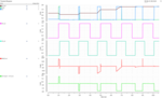
I plotted a signal called (Up - Down) in order to see when I have a phase difference.
I expect that when the phase difference pulse is very small, the capacitors load of the charge pump won't have enough time to charge, thus I don't expect a transition of the CP to happen.
I'm playing right now with the width of transistors to see if this changes something and also trying to make the phase difference small. in this example I used different frequencies for the sources.
I still don't know how to make the right plot in virtuoso to find the PFD characteristics function in order to calculate the dead zone, technically the right thing to do in my opinion is to plot the average current as a function of the (Up-Down) signal (phase difference).
it seems from the simulation that I get the opposite of what i'm expecting, as the phase error increases, the average current increases too. what did I do wrong ? and how I do technically plot this function ?
Hi everyone,
I read in many places including this Forum on ways how to plot the characteristics of PFD function:
I know that I need to decrease the phase difference between Clk_out and Clk_ref and see when the charge pump current/voltage doesn't change.
but it seems in my simulation a change happens every time, in this example the change kept happening until the capacitor at the output of
the charge pump was completely charged.
here are the schematics of my PFD and CP:
I'm using Virtuoso Custom IC Design Environment for Cadence.
I plotted a signal called (Up - Down) in order to see when I have a phase difference.
I expect that when the phase difference pulse is very small, the capacitors load of the charge pump won't have enough time to charge, thus I don't expect a transition of the CP to happen.
I'm playing right now with the width of transistors to see if this changes something and also trying to make the phase difference small. in this example I used different frequencies for the sources.
I still don't know how to make the right plot in virtuoso to find the PFD characteristics function in order to calculate the dead zone, technically the right thing to do in my opinion is to plot the average current as a function of the (Up-Down) signal (phase difference).
it seems from the simulation that I get the opposite of what i'm expecting, as the phase error increases, the average current increases too. what did I do wrong ? and how I do technically plot this function ?
Attachments
Last edited: