Continue to Site

Welcome to EDAboard.com

Welcome to our site! EDAboard.com is an international Electronics Discussion Forum focused on EDA software, circuits, schematics, books, theory, papers, asic, pld, 8051, DSP, Network, RF, Analog Design, PCB, Service Manuals... and a whole lot more! To participate you need to register. Registration is free. Click here to register now.

Voltage to frequency conversion using VFC32

Status
Not open for further replies.

Kartikpatel

Newbie level 3
Joined
Oct 10, 2019
Messages
4
Helped
0
Reputation
0
Reaction score
0
Trophy points
1
Activity points
37
Hi,

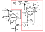
I am using VFC32 as Voltage to frequency. I want to make circuit that will convert 10 to 110 kHz signal in to 0 to 10V.
I was getting 10 kHz for 0V and 110 kHz for 10V but i didn't get linearity.
How to get linerity in VFC circuits.
Thanks.


Regrads,
Kartik patel
 

Hi,

Datasheet says it has good linearity.
Usually darasheets are correct.

We don't know your expectations regarding linearity.
We don't know how you measured your linearity and we don't know the measurement results.
We don't know your circuit.

You see we don't know much .... this makes it impossible to help.

Klaus
 

Hi,
Thanks for your reply.
Please find the attachment of the circuit I am using for voltage to frequency conversion.
I have set 10 kHz for 0V and 110 kHz for 10V. For the voltage between 1 to 9, I was getting some random frequency like 310 kHz for 2V, etc.
Also, the Behaviour of the practical circuit is not match with the theoretical calculation of Frequency output.

Fout= Vin/ 7.5 R1 C1

where; C1= One-shot capacitor(in my case 50 pF)
R1=Input resistor(in my case 50kΩ potentiometer)
Vin= Input voltage(0 to 10V)
 

Attachments

  • VFC Ckt.pdf
    234.9 KB · Views: 66

50 pF doesn't fit your formula. It get > 200 pF.

Did you check the integrator and pulse output waveforms? How do you measure frequency?
 

I also would ask the question: How did you measure the frequency? With a frequency enabled DMM? With an oscilloscope?

You really, and I mean really require to show us the output waveform with an oscilloscope.
If you only measured with a DMM, there could be multiple noise pulses or glitches that could be faking the readings.

Ask me how I know.
 

Hi,
I am using Keysight DSO-X 2024A for frequency measurement.
Now I am getting linearity for 0 to 10VDC. I am getting 10kHz for 0 V and 110 kHz for 10V.

Fout= Vin/ 7.5 R1 C1

where; C1= One-shot capacitor(in my case 285 pF)
C2= Integrating capaciotor(909µF)
R1=Input resistor(in my case 40kΩ )
Vin= Input voltage(0 to 10V)
I am getting good linearity.

Can you suggest me components selection for Frequency voltage conversion?
Please find a circuit for a frequency to voltage conversion.
 

Attachments

  • VFC prac ckt.PNG
    VFC prac ckt.PNG
    74.9 KB · Views: 79

[By calibrating the gain and offset potentiometer 50 k and 100 k respectively. ]Why now? What did you change?


µF? Really?[Yes; C2 as per the datasheet.

C2 (µF) =100/fFS; if fFS ≤ 100kHz; 0.001; if 100kHz < fFS ≤ 500kHz;
0.0005; if fFS > 500kHz or C2 = 10²/FMAX]
 

Status
Not open for further replies.

Similar threads

Part and Inventory Search

Welcome to EDABoard.com

Sponsor

Back
Top