Continue to Site

Welcome to EDAboard.com

Welcome to our site! EDAboard.com is an international Electronics Discussion Forum focused on EDA software, circuits, schematics, books, theory, papers, asic, pld, 8051, DSP, Network, RF, Analog Design, PCB, Service Manuals... and a whole lot more! To participate you need to register. Registration is free. Click here to register now.

300W SMPS with low input capacitance at the end of a 10km cable

Status
Not open for further replies.
T

treez

Guest
Hi,
We are bidding to do a power supply for a high temperature down hole situation. The spec is…

Vin = 500 to 1400V
Vout = 60V
Iout = 5A
Must be isolated output.
The supply cable leading to this buck converter is 10km long but could be as long as 100km….it will have a significant inductance.

(sorry but the above is all I have at the moment)

There won’t be much room for input capacitance, so there is going to be the problem of ringing between the supply cable and the input capacitance of the converter.
Due to the small input capacitance…..there may only be room for a few microfarads…..it is thought that having a front end stage comprising of an input current regulated buck converter may be advantageous….this would basically cancel out the effect of the input supply cable inductance. The output of this buck converter could then be used by a two transistor forward converter to supply the isolated 60V, 5A.

Would you say this would be the optimal way forward? There must be standard solutions for this kind of thing, which must be a well known situation “In the trade”.
 

Interesting question

The output is about 300 W
add about 10% over-design, 330 W
assuming 80% efficiency, the source, at input to the device, is about 413 W, or about 0.83 A at converter input

assuming a 10 AWG wire (2.588 mm diameter, nick-free soft annealed Cu wire having a tensile strength of 37000 pounds per square inch)
1 ohm per 1000 feet, or 3.28 ohm per km
at 100 km, that's 328 ohm for a total of 656 ohms of wire resistance
at 0.83 A, that's 542 V drop in the wire (1/2 from ground based source to device, and 1/2 back to ground based source)

so the actual source voltage has to be about 542 V (drop in wire) + 500 V (at converter input) at 0.83 A 860 W for 100 km
and about 54 V (drop in wire) + 500 V (at converter input) at 0.83 A 460 W for 10 km

sorry, don't know about "front end stage comprising of an input current regulated buck converter"
but I did build a current fed push pull one day, and made the mistake of having dead time
(as in a voltage fed push pull) instead of overlap time. it kept blowing up.
make sure you have a current path at all times (don't try to interrupt the current)
 
  • Like
Reactions: treez

    T

    Points: 2
    Helpful Answer Positive Rating
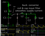
Theoretically you can send smooth DC 733 mA at 700V, by installing a suitable LC supply input filter. I reckon wire resistance upwards of 100 ohms (several miles of 14 AWG). It should hamper LC ringing tp some extent.

buck conv clk-driv swi 700V supply LC input smooth load 5A 62V.png

Although L & C values are small, the components need to be robust since they carry several Amperes, in high temperatures.
 

I’d say you have a space constrained energy storage problem. You may need to deliver a step or transient to your load but the input wiring can’t deliver in the short term. So you have no choice except to store transient energy locally.

Now the densest way to store energy I’d call an active filter. This could take a few forms but the key is to allow the caps you can fit to swing across their full voltage range, thus maximizing your usage of their energy.

So your constant current input stage creating an intermediary 250V nominal bus (allowed to swing between 100-400), or a parallel cap bank coupled with a buck-boost to your input (many little box designs did this) that actively smooths input current.
 

Hi,

Input voltage is DC? Or AC? Which waveform and frequency?

Klaus
 

I'm just curious. Do your design require a "instrict safety" ?
 

Vin is DC..

As you can imagine, this kind of hardware doesnt have standards applying to it.....its a remote power supply tunnelling far below the ground.
 

We have done this for subterranean feeds, 1km, 1800 - 3800VDC in, 350V 40A out, knowing the resistance of the feed wires is useful as it is easy to model and see the damping provided - usually heaps - hence the high max drive volts - to overcome the IR drop - your biggest problem is the ambient temp - we have always used resonant converters as this gives us the highest efficiency, lowest noise, and hence the least "extra" heat - the damping of the feed wires means that you can use just about any type of controller - volt mode, ave current mode, etc to control your converter
 

Thanks we thought of doing an LLC but were put off by the wide range of vin…..but then we could have an up-front converter to make vin constant.
Regarding LLC converters, (not that this was what you were talking about at all) we believe that they are best when vin and vout are constant…then one can switch at the Lr,Cr resonant frequency and have the LLC operating with minimal turn on and turn off switching losses……also, the voltage across the Cr cap is not overly high and the primary circulating current is minimal. The nice thing about operating at the Lr,Cr resonant frequency, is that the LLC converter works just like a standard transformer, with VIN/VOUT = NP/NS.
 

there are standard solutions for 1400V ( + safety margin ) to 60V - and 5 amps out is pretty easy - 1/2 bridge with cascaded devices ...
 
  • Like
Reactions: treez

    T

    Points: 2
    Helpful Answer Positive Rating
Status
Not open for further replies.

Part and Inventory Search

Welcome to EDABoard.com

Sponsor

Back
Top