Continue to Site

Welcome to EDAboard.com

Welcome to our site! EDAboard.com is an international Electronics Discussion Forum focused on EDA software, circuits, schematics, books, theory, papers, asic, pld, 8051, DSP, Network, RF, Analog Design, PCB, Service Manuals... and a whole lot more! To participate you need to register. Registration is free. Click here to register now.

UNKNOWN BYPASS problem

Status
Not open for further replies.

hamidkavianathar

Member level 5
Joined
Mar 6, 2016
Messages
89
Helped
0
Reputation
0
Reaction score
0
Trophy points
6
Activity points
804
hey guys
I have designed a custom board with a fpga. when I do initialize chain in iMPACT I recevice this message:
Attempting to identify devices in the boundary-scan chain configuration...
INFO:iMPACT - Current time: 9/28/2019 5:34:02 PM
PROGRESS_START - Starting Operation.
Identifying chain contents...INFO:iMPACT:1588 - '0':The part does not appear to be Xilinx Part.
'0': : Manufacturer's ID =Unknown , Version : 15
INFO:iMPACT:501 - '1': Added Device UNKNOWN successfully.
----------------------------------------------------------------------
----------------------------------------------------------------------
done.
PROGRESS_END - End Operation.
Elapsed time = 0 sec.
I have measured the voltage of all vcc pins. they are correct. but some IO pins have strange values. for example the voltage of them is 1.5 v.
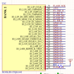
here is my schematic:
pic3.PNG
pic2.PNG
pic1.PNG
could you please tell what is wrong with my board?
thanks in advance.
 

1) A schematic with no resistor values is kind of useless. It’s also incomplete. Where do the JTAG signals go?
2) Have you looked at signals with a scope while initializing?
3) Unconfigured IO is floating; what voltage did you expect?
4) Try slowing down the clock speed and see if that helps.
5) These types of problems are often related to Pcb layout.
 
thanks berry for attention. you are right. this is my schematic:
3.PNG
1.PNG
I have checked the jtag signals on FPGA pins. they are electrically connected. I expect the IO pins be 0 or 3.3 volt. at least they should not change. but I have an led on board that some times is off and some times is on. I also slowed down the clock speed but it did not change.
 

Hi KlausST
thanks for the reply. I have checked it multiple times. I have measured them when I initialize the chain. they are constantly 3.3 and 1.2 volt.
I have used a very high quality PMIC in my board.
 

I have checked the jtag signals on FPGA pins. they are electrically connected.
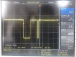
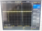
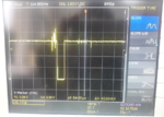
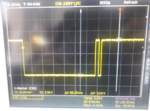
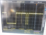
Did you check if TDO is activated at all and echoes TDI during chain identification or stays in tri-state?
 
yes I have checked it. I have taken photo of them.
TDI:
TDI.PNG
TDO:
TDO1.PNG

TDO2.PNG
TCK:
TCK.PNG
TMS:
TMS.PNG
 

I have a development board with the same FPGA that works properly. when I do "initialize chain" in my development board and my custom board, I see the exactly the same signals.
 
Last edited:

I have measured the voltage of all vcc pins. they are correct. but some IO pins have strange values. for example the voltage of them is 1.5 v.
here is my schematic:

Which pin(s) show 1.5V?

FYI TDI of the Xilinx USB platform cable is an output of the pod and and input for the FPGA, TDO is an input to the Xilinx USB platform cable and an output of the FPGA. If you switch them TDO(cable)-TDI(fpga) and TDI(cable)-TDO(fpga) then I would expect to see 1.5V when they are in contention.

thanks for comment. I have used a 4.7 k ohm resistor for pulling up HSWAPEN pin. now I changed it with a 330 ohm resistor and all of them are 0 volt.

- - - Updated - - -

in ug380 it is written that:
If JTAG is the only configuration mode, then PROGRAM_B, INIT_B, and DONE can be
tied High to a 330Ω resistor.
I also tried this configuration. but I still receiving the same message.
 

Status
Not open for further replies.

Similar threads

Part and Inventory Search

Welcome to EDABoard.com

Sponsor

Back
Top