aka_rabbi
Newbie level 5
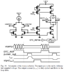
Hi. the attached picture is from the paper "K. Raczkowski, N. Markulic, B. Hershberg, J. Van Driessche and J. Craninckx, "A 9.2–12.7 GHz wideband fractional-N subsampling PLL in 28nm CMOS with 280fs RMS jitter," 2014 IEEE Radio Frequency Integrated Circuits Symposium, Tampa, FL, 2014, pp. 89-92.
doi: 10.1109/RFIC.2014.6851666"
i am trying to recreate the subsampling phase detection of this paper. However, in this transconductance amplifier, the Vsam values will be very low voltages(ideally 0v when the loop is in lock). So most of the time the amplifier will be off. That does not make sense to me. I am sure i have some misconception. If someone could correct me i would be very grateful.
