Continue to Site

Welcome to EDAboard.com

Welcome to our site! EDAboard.com is an international Electronics Discussion Forum focused on EDA software, circuits, schematics, books, theory, papers, asic, pld, 8051, DSP, Network, RF, Analog Design, PCB, Service Manuals... and a whole lot more! To participate you need to register. Registration is free. Click here to register now.

Can't stop LTC3780EG Buck-Boost regulator from oscillating

Status
Not open for further replies.

Plecto

Full Member level 5
Joined
Jan 4, 2012
Messages
315
Helped
1
Reputation
2
Reaction score
1
Trophy points
1,298
Activity points
4,979
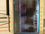
Hi. I'm using a LTC3780EG Buck-Boost regulator as a part of a MCU-controlled battery charging circuit. The circuit is apparently working fine with a steady output voltage, but it's efficiency is only around 75% and the duty cycle to the fets is swinging between 36 and 46% with a frequency of about 20khz. Right now I'm testing with an input voltage of 9V, output voltage of 13V and a resistive load of 33.3Ohm. The gate signal on Q1 does not look healthy either (image below). The components are on a 6-layer board with a solid ground plane. The controller along with all passive components are very close together on one side, with inductor and fets on the other. All traces are very short. What is causing this type of oscillation and what can I do?

Vg of Q40:
IMG_20190901_102945462.jpg

Vg of Q1:
IMG_20190901_103013898.jpg

Schematic:
Charge Regulator.jpg
 

Hi,

I know three things that can make your converter to oscillate that you might want to look at:

1) your feedback loop
2) your current sense resistor is too high and so your converter can't sustain the load current flow.
3) your load impedance is too low.

Show your output voltage so that we can understand what exactly you mean when you say "The circuit is apparently working fine with a steady output voltage..."
 

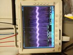
Here is the output. The 20khz oscillation is visible:

IMG_20190902_060651213.jpg

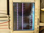
AC coupled:

IMG_20190902_060717710.jpg

The 0.01R current sense resistor is of the same value as the one the datasheets displays. It has to be of a certain value to get the correct over-current limit. How can the load impedance be too low? The regulator is supposed to be able to deliver 5A at 12.6V which is far more than it is right now.
 

Hi,

There is more than the schematic that determies whether a circuit is working as expected or not:
* PCB layout (Low impedace GND plane, capacitive coupling, kelvin wiring....)
* device types (ESR of capacitors, series inductance of resistors - like wire wound resistors)
* EMI, EMC
* and so on...

Klaus
 

I think I figured it out. My bootstrap diodes (D7 and D26) were no good. Either they couldn't supply the current or their reverse recovery time was too long, either way they failed to charge the bootstrap capacitor to no more than a couple of volts. This lead Q1 to only be partially ON which further lead to heavy ripple voltage at the input of the boost part of the regulator. Replacing the diode seemed to fix it :)
 

Congratulations on your success! I should have mentioned the bootstrap circuitry too.
 

Status
Not open for further replies.

Similar threads

Part and Inventory Search

Welcome to EDABoard.com

Sponsor

Back
Top