Continue to Site

Welcome to EDAboard.com

Welcome to our site! EDAboard.com is an international Electronics Discussion Forum focused on EDA software, circuits, schematics, books, theory, papers, asic, pld, 8051, DSP, Network, RF, Analog Design, PCB, Service Manuals... and a whole lot more! To participate you need to register. Registration is free. Click here to register now.

NodeMCU sinking current through DIO while power is off

Status
Not open for further replies.

smckinnon

Newbie level 4
Joined
Aug 16, 2019
Messages
6
Helped
0
Reputation
0
Reaction score
0
Trophy points
1
Activity points
57
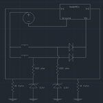
Hello, the issue I'm having with the circuit below is that the DIO pin is sourcing current while the push button is open. There are actually several push buttons that are arranged exactly as shown in the circuit below, but I've only shown one. The device is running on a battery, so I'm trying to have no current consumption while the push button is not being pressed. Could someone please take a look and offer some suggestions? Also, why is the input pin acting as a ground pin in this configuration while the power is off ??
Thanks!
ps. The purpose of the circuit is to detect which push button is being pressed, which will determine what the micro controller does when it's powered on.

NodeMCU_wiring_diagram.jpg
 
Last edited:

I'm hardly surprised, disconnecting the ground will almost certainly violate the maximum voltage and polarity ratings of the nodeMCU.
Consider that the DIO pin effectively becomes the ground (lowest potential) pin on the device while the supply is still present. You really need to switch the supply if you want to power it off but you are likely to run into a different problem, the time it takes from powering up to reading the switch.

nodeMCU is not a particularly low power device but you can do some tricks to reduce its consumption, for example putting it to sleep and awakening it when a button is pressed or using some external low power logic to read the switches then powering it up to read them. It really depends on what other things it has to do. Presumably you chose that device for its WiFi capability and you need to be aware that if takes quite a lot of current when the transmitter is turned on.

Brian.
 

I'm hardly surprised, disconnecting the ground will almost certainly violate the maximum voltage and polarity ratings of the nodeMCU.
Consider that the DIO pin effectively becomes the ground (lowest potential) pin on the device while the supply is still present. You really need to switch the supply if you want to power it off but you are likely to run into a different problem, the time it takes from powering up to reading the switch.

Thanks, could you explain how switching the ground violates the maximum voltage and polarity ratings?
Also, I had tried using a P Channel mosfet, but the issue I had was the supply voltage is 9 volts, and the allowable DIO voltage is 5 volts. I couldn't figure out how to drop the voltage to the input pin without consuming power when the device was off. What do you mean "you are likely to run into a different problem, the time it takes from powering up to reading the switch" ?

Also, the push button's I'm using are rated at 150mA @ 24Volts DC. I think a simple solution would be to remove the Mosfet completely and use the pb as a high side switch to Vin on the NodeMCU. The pb inputs could then be pulled low when the corresponding button isn't pressed (while off/booting), and go high to 3.3 volts using the zener configuration (consuming no power while off). I measured the current consumption and it didn't go above 300 mA for the time it was turned on (stays on for 4 second intervals). I believe the current rating of the button is increased by lowering the voltage to 9 volts, but I'm not sure what the limit would be. The naive solution of maintaining the same power rating is incorrect. I've emailed the manufacturer for their input, but haven't heard anything back... Any idea how to determine that?
Thx.
Sean

- - - Updated - - -

Like below. Just not sure if the button is rated for 300mA @ 9VDC, the spec only says 150mA @ 24VDC ?

NodeMCU_wiring_diagram2.jpg

- - - Updated - - -

One thing I didn't try when using the P Channel Mosfet was connecting the input to the drain (via the 3.3v zener). I had it connected to the gate of the Mosfet.
Does anyone see an issue with this idea below?

NodeMCU_wiring_diagram3.jpg
 

The voltage ratings and polarity limitations are from the DIO pins (and others) to the ground pin. Ask yourself what voltage will there be between DIO pins and ground if you connect the negative side of a 9V battery to the DIO pin and the positive side to Vin.
What will happen is conduction through paths on the board will make the ground pin float at some indeterminate voltage between 0V and 9V which will likely violate the ratings.

The switch current is not directly related to the voltage, at least at low voltages. However the nodeMCU, as you noticed, can draw about twice the switch rating which might work for a while but will likely result in welded contacts after a while.

What do you mean "you are likely to run into a different problem, the time it takes from powering up to reading the switch"
It depends to some extent on your program but consider that there will be some delay while the nodeMCU initializes after power is applied. If you are relying on the switch providing power it will have to be closed for long enough for the unit to initialize before its state can be read in and acted upon. For example, if the nodeMCU took 1 second to initialize but the switch was only held down for half a second, even if it did manage to start up, the switch would already have been released.

Brian.
 

I had tried using a P Channel mosfet, but the issue I had was the supply voltage is 9 volts, and the allowable DIO voltage is 5 volts. I couldn't figure out how to drop the voltage to the input pin without consuming power when the device was off.

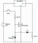
The above arrangement with diodes could do that with no need to add any transistor as simulated bellow, however not acting on GND, but rather on supply bus itself, so once any button is pressed, either the power input is supplied (channel A), the power is delivered to device (channel D), and you are able to determine which button were pressed (channels B and C):

Circuit.png

But obviously you should keep button pressed for a time enough to let the uC do its tasks, so you should provide on the code some way to sinalize (e.g with a LED) the accomplishment of the job.

Anyway, as Brian said, putting the uC into the sleep mode would be the suited approach, and the ESP8266 has what is called 'deep-sleep' mode, which would sink from the chip an average current of about ~20uA, a pretty small current.
 

Thanks for your help.
Brian, that makes more sense now. I guess I need a better understanding of how the uC hardware can switch between being an input and an output. I assumed there was some kind of isolating in place to prevent the pin from acting as a ground.
Andre, what's the purpose of the two capacitors in parallel with the zener diodes? Do these just help stabilize the input voltage to 3.3 volts?

The way I have the code setup, the user pushes and holds the button until the LEDs on the handheld indicate the task is complete (The ESP8266 is in station mode and quickly connects to the AP via a static channel and it's locked to the mac address of the AP. It then sends a modbus command to the appropriate register of an Allen Bradley MicroLogix PLC - the register that's written to is determined by which push button is pressed. The whole thing takes about 2 to 3 seconds.). If the user continues to push the button after the LEDs go out, the NodeMCU goes into deep sleep. The issue with using deep sleep continuously is that the NodeMCU draws far more power than just the ESP8266 alone would. If I recall, this is due to the UART and on board voltage regulator. The deep sleep current draw of the NodeMCU is 3mA (which is too much for my application).
Thx,
Sean
 

Status
Not open for further replies.

Similar threads

Part and Inventory Search

Welcome to EDABoard.com

Sponsor

Back
Top