Continue to Site

Welcome to EDAboard.com

Welcome to our site! EDAboard.com is an international Electronics Discussion Forum focused on EDA software, circuits, schematics, books, theory, papers, asic, pld, 8051, DSP, Network, RF, Analog Design, PCB, Service Manuals... and a whole lot more! To participate you need to register. Registration is free. Click here to register now.

How to drive vending Machine motor through MOSFET Driver Module?

Status
Not open for further replies.

sugandha123

Member level 1
Joined
Apr 10, 2019
Messages
38
Helped
0
Reputation
0
Reaction score
0
Trophy points
6
Activity points
306
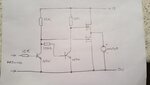
My vending Machine works with the Arduino and relay module to drive the motor. But relay output is not reliable and gives random switching sometimes. I am using 4 Channel relay Module. So, I want to replace relay Module to IRF520 Mosfet Module. But The main problem is, With Relay Module- Motor roates and comes at own its home location everytime when motor runs but............ With Mosfet module- Motor does not come at its own home location, everytime it changes its own position. I do know where is the issue. I have attached the block diagram of both the circuits with relay and with MOSFET. I have attached the Motor photo which I am using. IMG_20190808_181941-min.jpgIMG_20190808_182539-min.jpghKIsc.jpg
 

A guess:

the relay does two things - enables power to the motor AND it shorts out the motor when the power is off.
A short across the motor will work like a brake so it stops more precisely. To do it with a MOSFET isn't difficult, you need a half-bridge driver, basically another MOSFET across the motor that operates in the opposite sense to the one enabling the power but with a tiny delay between them so they can't both conduct at the same time.

Brian.
 

Hey

"basically another MOSFET across the motor that operates in the opposite sense to the one enabling the power but with a tiny delay between them so they can't both conduct at the same time"

Can you elaborate this with the circuit or anything?
 

Something like this. The NPN transistors can be small signal types (2N2222 etc), they invert and level shift the gate voltages.
Sorry for the sketch!

Brian.
 

Attachments

  • 20190808_223928.jpg
    20190808_223928.jpg
    27 KB · Views: 181
Something like this. The NPN transistors can be small signal types (2N2222 etc), they invert and level shift the gate voltages.
Sorry for the sketch!

Brian.

But Motor has 6 connections, What are the connection has to give to the motor?
 

Your photograph only shows two connections to the motor, the red wire and the black wire.

It isn't clear what the other connections are but I doubt they are going to the motor. Possibly they connect to limit switches but it isn't possible to tell from that view.

Brian.
 

qRRSp.jpg

See there are six pins and some pins are connected to the switch.
Six pins Nomenclature are:
1. Gnd
2. Common of switch
3. 12V supply
4. 12V supply
5. NC of switch
6. NO of switch

If I give input on Gnd and 12V the Motor run continuously.
And with relay when I give input on NO through relay by shorting C and NC of relay, then it rotates as per my code.
Now, what to do?
 

OK, so the motor has TWO connections, not six and the 'relay' is actually a switch is presumably driven by the mechanism.
What we don't know is how the switch operates with respect to the mechanism position or what the motor red and black wires are connected to.

I would guess it works like this: without power, the switch NC connects the 12V input to the motor. When power is applied, the motor rotates the mechanism until it reaches its end position, the switch NC then opens and stops the motor. When the 12V is then applied to the NO connection the motor continues back to it 'home' position where the switch again operates to stop it until the next cycle is started.

Can you see where the motor wires go to on the board?

Brian.
 

There are two wires which is connected with the motor.
Red and black wire.
Red wire is connected to the positive side of the diode and black wire is connected to the negative side of the diode.
 

Motor has two wire which is connected to positive and negative side of the diode.

And one more thing, Common of switch is connected to Gnd in this Motor.
And I want to run this motor through mosfet driver module.mosfet.jpg
 

Status
Not open for further replies.

Similar threads

Part and Inventory Search

Welcome to EDABoard.com

Sponsor

Back
Top